
The power grid is a crucial foundation and safeguard for modern economic development and social progress. The goal of building a strong and intelligent power grid is to construct a modern power grid system that is safe, environmentally - friendly, efficient, and interactive, to achieve the scientific development of the power grid, and to make the power grid a green platform for optimizing the allocation of energy resources, a service platform for meeting diverse user demands, and a fundamental platform for ensuring national energy security.
High - voltage circuit breakers are the most important and critical control and protection devices in the power system. Regardless of the state of the power line, such as no - load, loaded, or short - circuit fault, when required to operate, the circuit breaker should act reliably, either closing or opening the circuit. Its main functions are as follows:
The ZW32 - 12/630 - 20 outdoor high - voltage vacuum circuit breaker is a widely - used switching device in the current 12 kV distribution network. It adopts a three - phase pillar - type, fully - sealed structure, and features stable and reliable interrupting performance, a simple and concise appearance, light weight, small size, and suitability for pole - mounted installation. Due to its numerous advantages, it has won widespread favor among power users since its introduction to the market. Our company has also engaged in its production, with an annual sales volume of over 5,000 units. Based on the after - sales service in recent years, we have made some technical and technological improvements and refinements to the commonly - reported issues by users, which have been well - promoted and applied.
The key focus of the "12th Five - Year Plan" is transformation and upgrading. It advocates using high - tech to transform traditional industries, enhancing the core competitiveness of products through industrial transformation and upgrading, and promoting the orderly, healthy, and rapid development of the electrical engineering industry. At its 2005 work conference, the State Grid Corporation proposed "promoting standardized construction of the power grid, unifying technical standards for power grid engineering construction at all levels, promoting the application of typical designs, optimizing designs, saving investment, and improving efficiency." Therefore, taking customers as the focus of attention, actively responding to customer needs, and continuously improving and upgrading product quality in line with standards are urgent tasks for the high - voltage switch industry.
The design principles are: safety and reliability, advanced technology, reasonable investment, unified standards, and efficient operation. Efforts are made to achieve a coordinated unity of uniformity, reliability, advancement, economy, adaptability, flexibility, timeliness, and harmony.
In existing circuit breakers equipped with isolator switches, the isolator switches are all installed on the outgoing line side. This arrangement has the following drawbacks:
To address the above - mentioned technical issues, we have adopted the following technical solution, as shown in Figure 1.
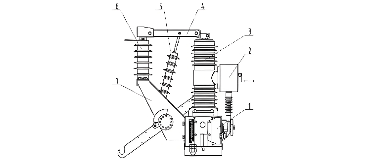
1.Circuit breaker mechanism box 2.Current transformer 3.Insulating post 4.Isolation knife switch 5.Insulating pull rod 6.Post insulator 7.Isolator switch support
The isolator switch is installed on the power supply side of the circuit breaker, and a reliable mechanical interlock is set between the isolator switch and the circuit breaker.
Generally, the current transformers of outdoor pole - mounted high - voltage vacuum circuit breakers have two installation structures: internal and external. Due to space limitations, most current transformers have a single - winding design, which makes it difficult for users to adjust the ratio according to the load in the future. This increases investment to some extent and causes a waste of resources.
To address this issue, we have made many innovations and designs in terms of structure and process technology.
The creepage distance (leakage distance) refers to the shortest distance along the insulating surface between two conductors. From the perspective of product reliability, air insulation is the most reliable. As long as the net insulation distances between conductors of different phases and between conductors and the ground are ensured, the insulation can be guaranteed.
Outdoor products operate under relatively harsh conditions and are exposed to various climatic conditions throughout the year. This makes them prone to mechanical or electrical problems, which directly affect the reliability and safety of power supply and normal production. Therefore, this factor should be fully considered in design and manufacturing to ensure the product's reliability in various environments.
In response to the above - mentioned situation, for all insulating parts of the outdoor switch directly exposed to the external environment, including bushings, current transformers, insulating pull rods, and post insulators, we have increased the density of the shed skirts. As a result, the creepage distance has reached 372 mm (as shown in Figure 1). This improvement enhances the overall structural insulation performance, expands the usage environment and locations of this type of vacuum circuit breaker, allowing it to be used in environments with high dust, high humidity, and heavy salt spray, and eliminates potential short - circuit risks caused by insulation issues.
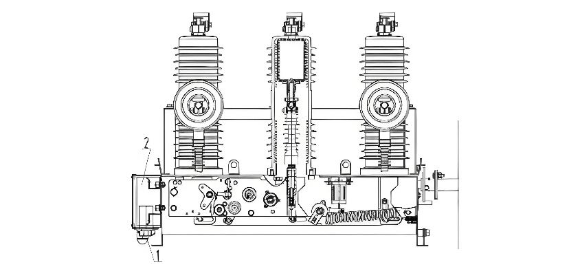
1.CT ratio conversion switch 2.Control box Front elevation view of the improved circuit breaker (Figure 2)
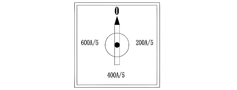
Figure 3 Schematic diagram of the CT ratio conversion switchNote: The "0" position indicates no protection and short circuit.
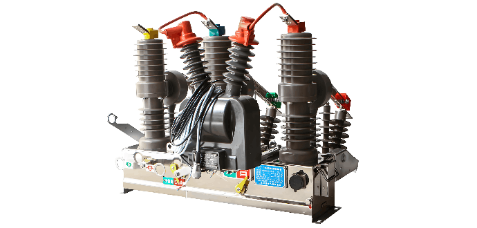
With the continuous expansion of the automation field in the power system, distribution network automation products have ushered in new development opportunities. Based on the ZW32 - 12/630 - 20 model, our company has independently developed a new product: the outdoor intelligent high - voltage vacuum circuit breaker. It is mainly composed of four major parts: the vacuum circuit breaker body, a three - phase integrated zero - sequence current transformer, an FDK - type controller, and an external voltage transformer, as shown in Figure 5.
This intelligent circuit breaker is widely used in 10 kV urban and rural overhead loop network lines. It can serve as a sectional isolating switch and a tie switch, and is an automated switching device that enables the automatic allocation of load in the loop network lines. In the branch lines supplying large users, it can be used as a boundary switch (commonly known as a "watchdog"). In the overhead feeder distribution network, it can function as a recloser and a sectionizer.
The boundary circuit breaker features a remote management mode, protection control functions, and communication functions. It can reliably detect and judge zero - sequence currents in the milliampere range and phase - to - phase short - circuit fault currents within its boundary. It can automatically cut off single - phase grounding faults and phase - to - phase short - circuit faults, ensuring the stable and reliable operation of the power grid.
Outdoor high - voltage vacuum circuit breakers use overhead connections for both incoming and outgoing lines. They offer advantages such as small footprint, clear layout, convenient operation and maintenance, fewer structures, and fast construction and installation. During the design and manufacturing processes, continuous improvement and optimization of various performance aspects should be carried out to achieve excellence, ensuring the safe and reliable operation of the product.


