Daga shekarar 2009 zuwa 2010, State Grid ta cikin yanayin mulkin hanyoyin smart grid, tana neman hanyoyin mulki na smart grid mai kyau, tana kula da bincike da fasahar teknologi, girman abubuwa, da kuma kula da ayyuka a fannan dukkan. Daga shekarar 2011 zuwa 2015 an yi ayyukan daɗi, wanda a lokacin da suka shiga hanyoyin mulki na smart grid, da aka fara da takalma da al'adu na gudanar da masu amfani, da kuma samun yadda ake iya amfani da teknologi da abubuwan da suka samu nasara.
Daga shekarar 2016 zuwa 2020, ya zama hanyoyin tsarkake da ingantaccen, inda an yi tasirar da sabbin smart grid, da teknologi da abubuwan da suka samu nasara a matsayin ma'aikatar jagoranci. A lokacin, ya zama da ake iya gudanar da kayan aiki a jinkiri masu amfani. Don in tabbatar da ayyukan da ake bukata don hanyoyin mulki na smart grid, ana bukata cewa mafi girman circuit breakers da ake sa a kan jerin gwamnati suna iya haɓaka da ingantaccen protection mai kyau, wanda yake da lalace mai kyau, yana nufin cewa akwai adadin aiki mai kyau ga primary operating current value.
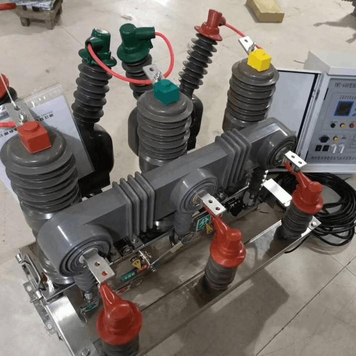
Saboda haka, a cikin har hanyar dukkan, akwai current transformer da take da differential protection, outdoor pole-mounted vacuum circuit breakers sun buƙata da residual current transformers don microcomputer protection don in ba da precise leakage protection. Residual current transformers na zaman ce suna da ƙwarewa mai yawa, karamin ƙwarewa mai yawa, da kuma lalace mai yawa.
Akwai matsalolin da suka cutar da aikinsu, hakan da take da faɗa a kan aiki, da kuma karamin length of secondary lead circuits, ba su iya tabbatar da ayyukan da ake bukata don microcomputer protection. Yanzu, dukkan outdoor circuit breakers da suka iya tabbatar da ayyukan da ake bukata don hanyoyin mulki na smart grid na gwamnati, suna da ake girma a kan kamfanoni na darasi, wanda yake da ƙarfin aiki mai yawa. Don in iya haɓaka da ayyukan da ake bukata, yana buƙata a yi girman outdoor circuit breakers da suka iya tabbatar da ayyukan da ake bukata.
Yanzu, wasu littattafai da muna buƙata a yi shi shine girman residual current transformers don microcomputer protection, da za su iya amfani a cikin small spaces, da kuma high-sensitivity leakage microcomputer protection, da kuma accurate operation, da kuma karin a yi localization of residual current transformers don microcomputer protection.
Residual current transformer (zero-sequence current transformer) shine current transformer mai hususan da aka yi don in yi transform residual current (zero-sequence current). Ana amfani da shi don single-phase grounding protection a cikin neutral-insulated systems. An yi three-phase conductors da take da core window of the transformer simultaneously, wanda yake da primary winding of the transformer.
Idan system ta yi aiki daidai, sum of the three-phase currents yana zama zero, da kuma babu output from the secondary side of the residual current transformer. Idan an yi single-phase grounding fault a cikin line, primary current of the residual current transformer yana zama minimum operating current of the relay or microcomputer protection, wanda yake da trigger the protection device to act.
Ba haka ba, yana zama inactive. A cikin residual current transformers na zaman ce, secondary side yana da direct connection to a relay. Saboda number of turns in the primary winding of the transformer yana zama 1, number of turns in the secondary winding yana zama very small. Minimum primary operating current of traditional residual current transformers yana zama mostly between 2.4A and 10A, and rated primary current of traditional residual current transformers is generally selected in the range of 15A to 300A. To meet the accuracy requirements, core cross-sectional area of the transformer is designed to be relatively large, resulting in a large size, heavy weight, low accuracy, and small secondary load.
Idan fault current yana zama less than 2.4A, current output by the traditional transformer is insufficient to activate the relay, creating a "dead zone." Therefore, to enable the transformer to provide accurate protection for the microcomputer within a wide range of operating currents without a dead zone, it is necessary to design a special residual current transformer that can be used in conjunction with microcomputer protection.
Restricted by the installation space of the circuit breaker, the special residual current transformer used with microcomputer protection not only needs to be small in size and light in weight but also requires high-precision secondary output and a large secondary load. Generally, the primary operating current of the transformer is required to be between 0.2A and 10A. If the transformer can ensure good linearity and sensitivity under the condition of a large secondary load output, it can meet the requirements of microcomputer protection and avoid the occurrence of a "dead zone."
Outdoor pole-mounted vacuum circuit breakers are generally installed outdoors and are far from the supporting automation devices. However, the load required by the microcomputer protection itself is very low. When designing the residual current transformer, the rated load mainly considers the load of the secondary lead circuit of the transformer. Since the microcomputer protection device is usually far from the pole-mounted circuit breaker installed outdoors, the rated load of the transformer is generally selected to be relatively large, with the maximum reaching about 200Ω (this load can be determined according to the actual situation of the user).
Residual current transformers for microcomputer protection require extremely high sensitivity and must respond promptly and accurately. Sensitivity refers to the ability of the secondary winding of the transformer to respond to leakage current, which can be described as follows: under a certain amount of leakage current, the higher the induced electromotive force of different transformers, the higher their sensitivity.
Sensitivity is related to the number of turns of the primary and secondary windings of the transformer. The more turns in the secondary winding, the higher the sensitivity. The residual current transformer is directly installed on the three-phase primary conductors, and the primary wire is the protected line, with the number of primary turns being 1. Increasing the number of primary turns is not practical.
The induced electromotive force of the secondary winding, U2=4.44f⋅N2⋅μ⋅I1⋅S, where:
I1represents the rated primary current.
S is the cross-sectional area of the iron core.
muis the magnetic permeability.
f is the frequency.
N2 is the number of turns of the secondary winding.
As can be seen from the formula, due to the limitations of the installation position of the transformer, the external dimensions of the transformer cannot be very large. Thus, the cross-sectional area of the iron core of the transformer is relatively small. To enhance the sensitivity of the transformer, it is necessary to either increase the number of turns of the secondary winding or improve the magnetic permeability of the iron core of the transformer.
The rated primary current of outdoor circuit breakers is basically 630A or less. Given the small cross-sectional area of the iron core of the transformer, in order to ensure high sensitivity, through experiments, the number of turns of the secondary winding is generally initially set between 1500 and 2000 turns. The specific number of turns can be determined according to the secondary load and the secondary output voltage of the transformer required by the microcomputer.
Once the cross-sectional area of the iron core, the number of turns, and the secondary load are determined, the parameter that affects the secondary induced electromotive force (i.e., sensitivity) of the
transformer is only related to the magnetic permeability of the iron core. Therefore, determining the material of the iron core used in the transformer is of crucial importance. The linearity and residual characteristics of the transformer mentioned later are also closely related to the material of the iron core.

Analyzing the data in Table 1, both nanocrystalline alloy and Metglas have the highest magnetic permeability. However, Metglas has a relatively low saturation induction intensity and is also expensive in the market. Considering comprehensively, we preferentially select nanocrystalline alloy as the material.The sensitivity of the transformer is not only directly proportional to the magnetic permeability of the iron core but also has a direct relationship with the shape of the iron core and the length of the magnetic circuit.
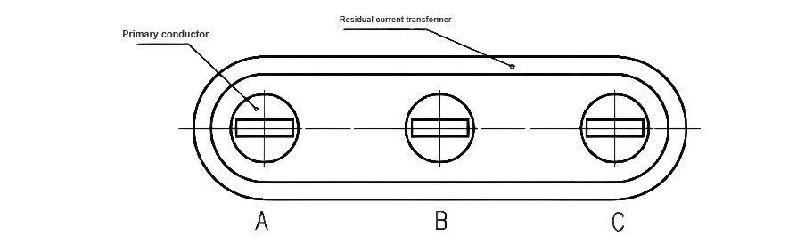
Generally, apart from using high-permeability materials for the iron core to enhance the transformer's sensitivity, we also try to shorten the magnetic circuit of the iron core as much as possible to reduce magnetic leakage and ensure the utilization rate of the iron core. Under normal circumstances, a circular iron core has the shortest magnetic circuit. However, since the three-phase primary conductors of the outdoor pole-mounted circuit breaker are arranged side-by-side in a line, when space permits, the iron core should be designed as an ellipse based on the arrangement shape and spacing of the three-phase primary conductors of the circuit breaker. The shape of the transformer and its positional relationship with the primary conductor are shown in Figure 1.
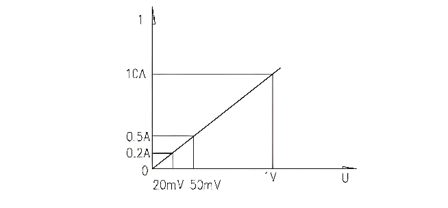
The residual current transformer should be able to respond quickly to abnormal leakage states in the circuit and provide an actionable voltage signal to the microcomputer protection device. The transformer must have good linearity to truly reflect the operating status of the circuit. Linearity refers to the ratio of the change in the input current to the change in the output voltage of the transformer being a constant, as shown in Figure 2.
transformer is only related to the magnetic permeability of the iron core. Therefore, determining the material of the iron core used in the transformer is of crucial importance. The linearity and residual characteristics of the transformer mentioned later are also closely related to the material of the iron core.
In the circuit, the minimum primary operating current of the circuit breaker is generally required to be below 10A. Therefore, it is generally required that when the primary current of the transformer is below 10A, the better the ratio of the change in the input current to the change in the output voltage of the transformer is linear, the more it can meet the usage requirements. The linearity requirement of the transformer needs repeated testing.
Under the condition of a certain magnetic permeability of the iron core and secondary load, the voltage output of the transformer is ensured to change linearly by adjusting the cross-sectional area of the iron core or the number of secondary turns. However, in actual circuits, there are often other factors that affect the transformer from providing an accurate voltage signal to the microcomputer protection device.
When the transformer is installed, it needs to be sleeved on the three-phase conductors arranged side-by-side in a line. When the primary conductor passes the rated current, the residual current transformer will be interfered by the magnetic fields generated by the three-phase currents simultaneously, and the local magnetic flux density of the iron core will increase. If the local part of the iron core is oversaturated, the linearity of the transformer will deteriorate, seriously affecting the magnitude of the secondary output voltage. As a result, the microcomputer protection may malfunction or fail to operate.
During actual operation, after the residual current transformer is impacted by a large-scale ground-fault current, and after the protection action is completed and power supply is restored for continued operation, if the technical parameters of the transformer cannot return to the state before the impact, that is, there is residual magnetism in the iron core of the transformer, it will seriously affect the accurate action of the leakage protector next time.
When designing this residual current transformer, the following points should be noted:
The iron core is preferably made of nanocrystalline alloy with high magnetic permeability and low residual magnetism. This material has good overload characteristics and can easily return to the initial magnetic state under over-current impact. The residual voltage of the transformer can be controlled and detected not to be too large by simulating the passage of various ground-fault currents on the primary side. However, the residual voltage of the transformer generally increases with the increase of the rated primary current. But after the iron core reaches magnetic saturation, the residual voltage on the secondary side of the transformer will increase sharply.
When designing the transformer, in order to minimize the influence of the primary current on the residual voltage value of the residual current transformer, when choosing nanocrystalline alloy with high magnetic permeability and low residual magnetism to make the iron core, measures such as appropriately increasing the cross-sectional area of the iron core or reducing the internal resistance of the secondary winding can be taken jointly to reduce the residual voltage of the residual current transformer.