Nominal Voltage: What is it?

Electrical4u
03/08/2024

What is Nominal Voltage?

Nominal voltage is a value assigned to a circuit or system to designate its voltage class conveniently(e.g. 120/240 volts, 300 volts, 480Y/277 volts). The actual voltage at which a circuit operates can vary from the nominal voltage within a range that permits satisfactory operation of equipment.

The word “nominal” means “named”. It is not the precise operating or rated voltage. i.e. a 240-volt circuit may not be precisely 240.0000 volts, and may instead operate at 235.4 volts.

A nominal quantity (e.g. length, diameter, voltage) is generally the quantity according to which some item has been named or is generally referred to.

Nominal voltage is used as a voltage reference to describe batteries, modules, or electrical systems. This is the supply circuit system voltage to which the unit may be connected. You may consider it an “approximate” or “average” voltage level (although it is not technically the “average”).

image.png

Nominal Voltage vs Rated Voltage

The voltage level of an electrical power system is known as Nominal Voltage. It is also known as system voltage. In 3-phase systems, the voltage between the external lines is known as the nominal voltage.

The voltage range for which the equipment is designed to operate under the stable condition by giving reliability is known as rated voltage. Thus the rated voltage of any electrical equipment is the highest voltage at which equipment can function within its thermal limit without endangering the life of the equipment.

When designing the device, the designer should take the voltage safety margin into consideration for operation of equipment within the range of rated voltage.

The rated voltage value must be greater than the nominal voltage, for the safe functioning of the equipment. The difference between the nominal and rated voltages must be large enough to study the variations in the nominal voltage on the power lines.

To have a better insight on rated voltage, consider the working of a circuit breaker circuit. An electrical circuit breaker is a switching device which can be operated manually and automatically for controlling and protecting an electrical power system. Depending on the insulation system of a circuit breaker, the rated voltage of the circuit breaker varies.

The circuit breaker is designed to operate at the highest RMS voltage, which is known as the rated maximum voltage of the circuit breaker. This value is above the nominal voltage for which the circuit breaker is designed and is the upper limits for operation. The rated voltage is depicted in kV RMS.

In short, the ‘rated voltage’ is the maximum voltage that the circuit-breaker can interrupt safely and without being damaged by unnecessary arcing. Whereas the ‘nominal voltage’ is the voltage for which the circuit-breaker is designed to be used.

Nominal Voltage vs Operating Voltage

The voltage at which equipment is being operated is known as operating voltage. For reliable working of equipment, it must be operated within the range of rated voltage. The operating voltage is the actual voltage applied at the equipment terminal.

A multimeter is used to measure the voltage at the equipment terminal. If the applied voltage is greater or lower than its rated voltage, the performance of the equipment is affected.

As a concluding example for 132 kV power system, a circuit breaker is installed with the following specifications. When the operating voltage is not within the range of rated voltage, equipment operation is affected.

Nominal Voltage – 132 kV
Rated Voltage – 132 kV +/- 10 % [118.8 – 145.2 kV ]
Operating Voltage – Can be in the range of 118.8 to 145.2 kV.

What is the Nominal Voltage of a Battery?

A battery is an electrochemical device which generates a voltage potential when placing metals of various affinities in an acid solution.

For example, a battery that has an actual voltage of 1.62 V but commonly it is referred to as a “1.5-volt battery”, which means that the battery has a nominal voltage of 1.5 V. Another example is the term “DC 12V” describes a 12V battery, regardless of whether it is fully charged (13.7 Vdc) or discharged (10Vdc).

Source: Electrical4u

Statement: Respect the original, good articles worth sharing, if there is infringement please contact delete.


Electrical4u

Electrical4U is dedicated to the teaching and sharing of all things related to electrical and electronics engineering.

What is a Pure Resistive AC Circuit?
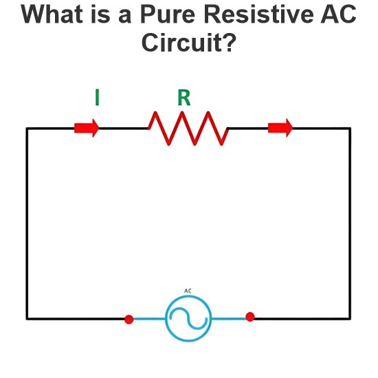
Pure Resistive AC CircuitA circuit containing only a pure resistanceR(in ohms) in an AC system is defined as a Pure Resistive AC Circuit, devoid of inductance and capacitance. Alternating current and voltage in such a circuit oscillate bidirectionally, generating a sine wave (sinusoidal waveform). In this configuration, power is dissipated by the resistor, with voltage and current in perfect phase—both reaching their peak values simultaneously. As a passive component, the resistor neither
Edwiin
06/02/2025
What is a Pure Capacitor Circuit?
Pure Capacitor CircuitA circuit comprising only a pure capacitor with capacitanceC(measured in farads) is termed a Pure Capacitor Circuit. Capacitors store electrical energy within an electric field, a characteristic known ascapacitance(alternatively referred to as a "condenser"). Structurally, a capacitor consists of two conductive plates separated by a dielectric medium—common dielectric materials include glass, paper, mica, and oxide layers. In an ideal AC capacitor circuit, the current
Edwiin
06/02/2025
Resistance Switching in a Circuit Breaker
Resistance SwitchingResistance switching refers to the practice of connecting a fixed resistor in parallel with the contact gap or arc of a circuit breaker. This technique is applied in circuit breakers with high post-arc resistance in the contact space, primarily to mitigate re-striking voltages and transient voltage surges.Severe voltage fluctuations in power systems arise from two main scenarios: interrupting low-magnitude inductive currents and breaking capacitive currents. Such overvoltages
Edwiin
05/23/2025
What is Biot Savart Law?
The Biot-Savart Law is employed to determine the magnetic field intensity dHnear a current-carrying conductor. In other words, it describes the relationship between the magnetic field intensity generated by a source current element. This law was formulated in 1820 by Jean-Baptiste Biot and Félix Savart. For a straight wire, the direction of the magnetic field adheres to the right-hand rule. The Biot-Savart Law is also referred to as Laplace’s law or Ampère’s law.Conside
Edwiin
05/20/2025
Inquiry
Download
IEE-Business is dedicated to serving the personnel in the global power industry.
Join IEE-Business, not only can you discover power equipment and power knowledge, but also canhnd like - minded friends!