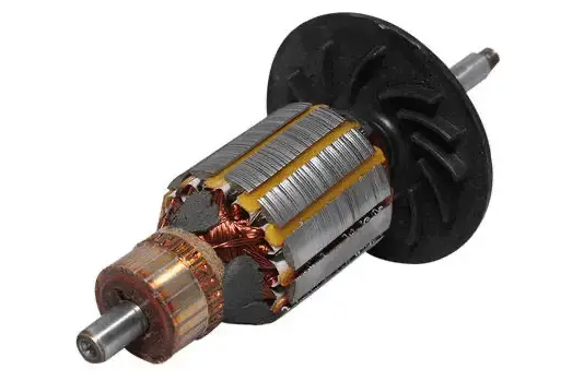
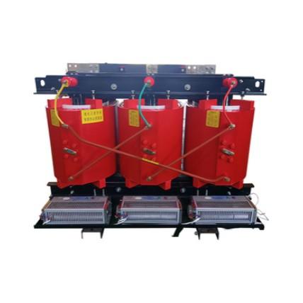
Armature shi wani batu na makina mai karamin sashi (ya'ni, motor ko jenereta) wanda yake taka shiga sashi mai kawo-kawo (AC). Armature ta kawo AC hatta a cikin makina mai DC (Direct Current) saboda commutator (wanda yana kawo-karfin sashi a lokacin da ya gama) ko saboda electronic commutation (misali, a cikin brushless DC motor).
Armature ta bayan abinci da dukkana armature winding, wanda yake tafi sama da magnetic field wanda an tsara a cikin air gap daga stator zuwa rotor. Stator zai iya zama wani batu mai karama (rotor) ko wani batu mai rike (stator).
Sun fada sunan armature a shekarar 19th don nuna ma'anin “keeper of a magnet”.

Electric motor ta kawo energy mai karamin sashi zuwa energy mai karfi tare da amfani da principle of electromagnetic induction. Idan kungiyar da ke shiga sashi ana karkashin magnetic field, yana samu force kamar yadda ake nuna a cikin Fleming’s left-hand rule.
A cikin electric motor, stator ta kawo rotating magnetic field tare da amfani da permanent magnets ko electromagnets. Armature, wanda yana zama rotor, ta kasa armature winding wanda yake taka shiga commutator da brushes. Commutator ta kawo-karfa direction of the current a cikin armature winding idan yake kawo-kawo don haka yana tafi sama da magnetic field.
Sama-sama daga magnetic field da armature winding ta kawo torque wanda yake kawo-kawo armature. Shaft wanda ake kasa armature ta kawo mechanical power zuwa wasu devices.
Electric generator ta kawo mechanical energy zuwa electrical energy tare da amfani da principle of electromagnetic induction. Idan kungiyar ta kawo-kawo a cikin magnetic field, yana kawo electromotive force (EMF) kamar yadda ake nuna a cikin Faraday’s law.
A cikin electric generator, armature yana zama rotor wanda yake kawo-kawo saboda prime mover, misali, diesel engine ko turbine. Armature ta kasa armature winding wanda yake taka shiga commutator da brushes. Stator ta kawo stationary magnetic field tare da amfani da permanent magnets ko electromagnets.
Relative motion daga magnetic field zuwa armature winding ta kawo EMF a cikin armature winding, wanda yake kawo electric current through the external circuit. Commutator ta kawo-karfa direction of the current a cikin armature winding idan yake kawo-kawodon haka yana kawo alternating current (AC).
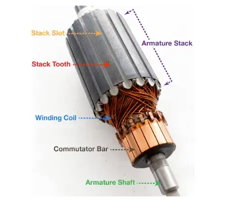
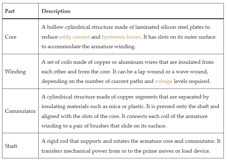
Armature ta kasance da four main parts: core, winding, commutator, and shaft. A diagram of an armature is shown below.


Armature of an electric machine ta kawo various types of losses wanda suke ci gaba da efficiency da performance. The main types of armature losses are:
Copper loss: This is the power loss due to the resistance of the armature winding. It is proportional to the square of the armature current and can be reduced by using thicker wires or parallel paths. The copper loss can be calculated by using the formula:

where Pc is the copper loss, Ia is the armature current, and Ra is the armature resistance.
Eddy current loss: This is the power loss due to the induced currents in the core of the armature. These currents are caused by the changing magnetic flux and produce heat and magnetic losses. The eddy current loss can be reduced by using laminated core materials or increasing the air gap. The eddy current loss can be calculated by using the formula:

where Pe is the eddy current loss, ke is a constant depending on the core material and shape, Bm is the maximum flux density, f is the frequency of flux reversal, t is the thickness of each lamination, and V is the volume of the core.
Hysteresis loss: This is the power loss due to the repeated magnetization and demagnetization of the core of the armature. This process causes friction and heat in the molecular structure of the core material. The hysteresis loss can be reduced by using soft magnetic materials with low coercivity and high permeability. The hysteresis loss can be calculated by using the formula:

where Ph is the hysteresis loss, kh is a constant depending on the core material, Bm is the maximum flux density, f is the frequency of flux reversal, and V is the volume of the core.
The total armature loss can be obtained by adding these three losses:

The armature efficiency can be defined as the ratio of the output power to the input power of the armature:

where ηa is the armature efficiency, Po is the output power, and Pi is the input power of the armature.
The design of the armature affects the performance and efficiency of the electric machine. Some of the factors that influence the armature design are:
The number of slots: The slots are used to accommodate the armature winding and provide mechanical support. The number of slots depends on the type of winding, the number of poles, and the size of the machine. Generally, more slots result in better distribution of flux and current, lower reactance and losses, and smoother torque. However, more slots also increase the weight and cost of the armature, reduce the space for insulation and cooling, and increase the leakage flux and armature reaction.
The shape of slots: The slots can be opened or closed, depending on whether they are exposed to the air gap or not. Open slots are easier to wind and cool, but they increase the reluctance and leakage flux in the air gap. Closed slots are more difficult to wind and cool, but they reduce the reluctance and leakage flux in the air gap.
The type of winding: The winding can be a lap wound or wave wound, depending on how the coils are connected to the commutator segments. Lap winding is suitable for high-current and low-voltage machines, as it provides multiple parallel paths for current flow. Wave winding is suitable for low current and high voltage machines, as it provides a series connection of coils and adds up the voltages.
The size of the conductor: The conductor is used to carry the current in the armature winding. The size of the conductor depends on the current density, which is the ratio of current to cross-sectional area. Higher current density results in higher copper loss and temperature rise, but lower conductor cost and weight. Lower current density results in lower copper loss and temperature rise, but higher conductor cost and weight.
The length of the air gap: The air gap is the distance between the stator and rotor poles. The length of the air gap affects the flux density, reluctance, leakage flux, and armature reaction in the machine. Smaller air gap results in higher flux density, lower reluctance, lower leakage flux, and higher armature reaction. Larger air gap results in lower flux density, higher reluctance, higher leakage flux, and lower armature reaction.
Some of the methods used to design the armature are:
EMF equation: This equation relates the induced EMF in the armature to the flux, speed, and number of turns of the winding. It can be used to determine the required dimensions and parameters of the armature for a given output voltage and power.

where Ea is the induced EMF in volts, ϕ is the flux per pole in webers, Z is the total number of conductors in series, N is the speed of rotation in rpm, P is the number of poles, and