1 Overview
Distribution network safety has long been under - addressed, with its automation lagging substation automation . Using 10 kV intervals of existing substations to set line section points meets future grid needs . Configuration of distribution switches, section switches, and protection must match substation outgoing - line protection for reliability. Fault isolation, self - healing, and restoration are key to distribution automation .
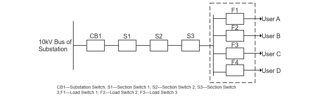
Scholars have studied smart distribution network fault - restoration optimization (multi - power, intermittent sources, energy storage) , but not load - switch - based user - equipment fault isolation. Take Figure 1’s line: Section switch S3 serves A, B, C. A’s fault triggers S3 tripping. Transient faults allow successful reclosing; permanent ones cause B/C outages, harming production, cutting supply, and adding troubleshooting (as S3 can’t pinpoint the fault, requiring one - by - one checks).Thus, a load - switch method/device is urgently needed to isolate faults, identify faulty users. Ensure S3 recloses successfully for non - faulty users, regardless of user/fault type (transient/permanent).
2 Method for Effectively Isolating Power User Equipment Faults with Load Switches
A load switch, a switching device between a circuit breaker and an isolating switch, has a simple arc - extinguishing device. It can interrupt rated load current and some overload current but not short - circuit fault current. So, when any user equipment fails, only section switch S3 trips for protection. If a device detects the faulty user and trips its load switch before S3 recloses, the faulty user is isolated, S3 recloses successfully. Sending faulty user info to distribution network operation & maintenance (O&M) personnel via text message lets them handle faults quickly, reducing O&M workload, improving power supply reliability, and ensuring non - faulty users’ power supply.
3 Technical Route for Effectively Isolating Power User Equipment Faults with Load Switches
3.1 Technical Logic Module Process
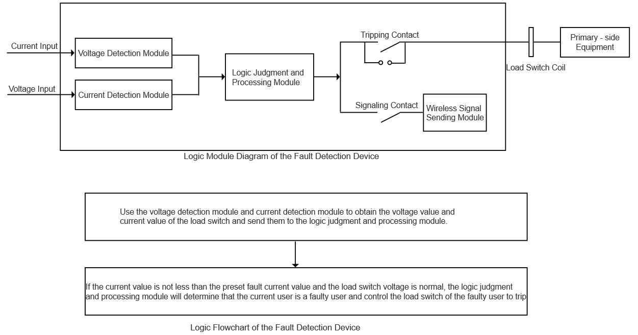
Take User A’s equipment fault as an example. Install a fault detection device at its load switch (as in Figure 2). Set between the load switch and incoming line, it has a voltage detection module, current detection module, logic judgment & processing module, tripping contact, signaling contact, and wireless signal sending module (logic process in Figure 3). Outputs of voltage and current detection modules connect to the logic module’s input. Its output connects to one end of the tripping contact and signaling contact. The tripping contact’s other end connects to the user’s primary equipment via the load switch’s tripping coil; the signaling contact’s other end connects to the wireless module. This enables effective fault isolation, quick fault handling by maintenance staff, reduced fault - finding workload, and improved work efficiency.
3.2 Physical Wiring Implementation
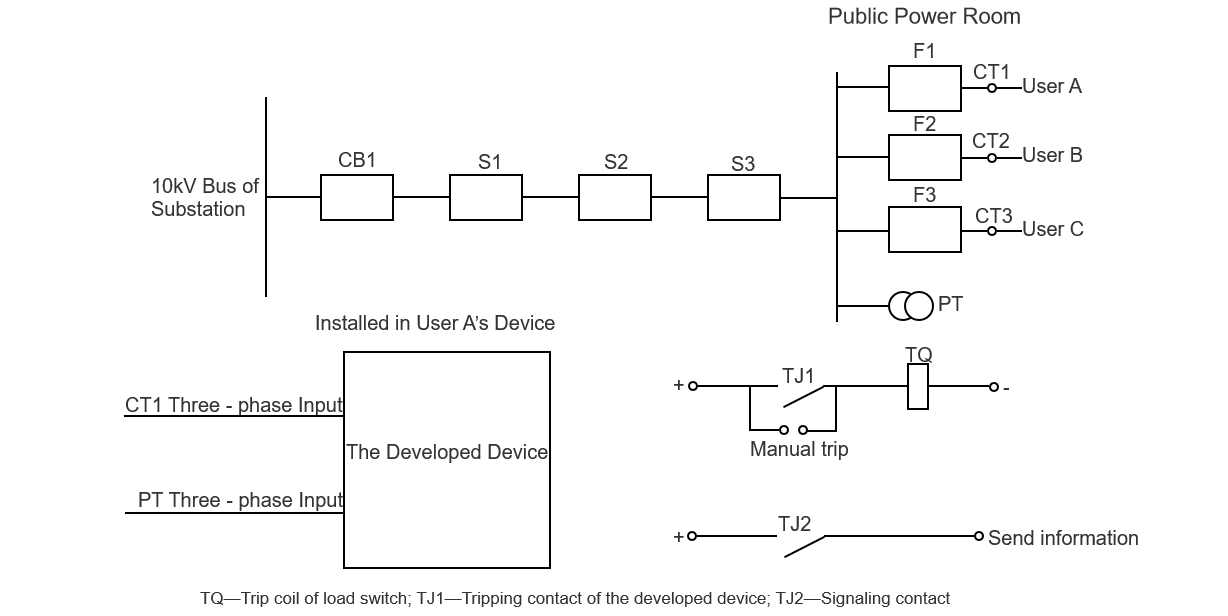
Taking User A’s equipment fault as an example (see Figure 4), the voltage detection module connects to the bus voltage transformer of the public power distribution room, and the current detection module connects to CT1 (current transformer of User A’s incoming line). User A’s logic judgment module processes the input current and voltage.
When User A has a short - circuit fault, the current through its logic judgment module surges to (and exceeds) the preset fault current, marked as “1”. Then, section switch S3 trips, causing the public distribution room bus to lose voltage. All users’ logic modules detect this voltage loss (marked “1”), but only User A’s module detects both fault current and voltage loss (both “1”). These “1s” form an AND gate, identifying User A as faulty.
User A’s logic module outputs tripping contact TJ1 and signaling contact TJ2. TJ1 closes, connecting to the positive power supply and load - switch tripping coil to trip User A’s load switch. TJ2 closes, sending fault info to distribution network O&M staff via wireless. This ensures the faulty user’s load switch doesn’t interrupt fault current yet isolates the fault. Non - faulty users, despite voltage loss (no fault current detected), don’t trip their load switches (AND gate not activated).
Similarly, the secondary currents of incoming line current transformers CT2 (User B) and CT3 (User C) connect to the detection device. The fault logic follows User A’s principle, isolating faults for B/C to ensure others’ normal power supply.
4 Coordination with Section Switch Protection & Anti - Maloperation Measures
For overhead lines: The fault detector coordinates with S3’s reclosing time (typically 1.2s delay post - trip). Within 1.2s, it must trip the faulty user’s load switch (preventing S3 from reclosing on faults). Fault info is texted to O&M staff for quick repairs.
For cable lines: Since S3 has no reclosing, the detector trips the faulty load switch and texts fault info. O&M staff then close S3, ensuring non - faulty users’ power and reducing outage time.
To avoid mis - tripping non - faulty load switches after S3 recloses: The detector’s logic requires first sensing fault current surge, then voltage loss (forming an AND gate). A delay is added to voltage loss judgment (to prevent mis - trips from inrush current reaching before voltage).
5 Conclusion
Installing fault detectors at users’ incoming line load switches (coordinated with section switch protection) lets load switches auto - isolate faults and alert O&M staff. This boosts public distribution line reliability, cuts troubleshooting workload, and limits outage spread. The device can also be used on main distribution line load switches (coordinated with upper - level section switch protection), isolating post - load - switch faults and ensuring power for users between switches. This shrinks outage ranges and improves distribution line reliability.