1 Overview of EMC Performance of Electronic Voltage Transformers
1.1 Definition & Requirements of EMC
Electromagnetic Compatibility (EMC) denotes a device/system’s ability to operate undisturbed in a given electromagnetic environment and avoid causing unacceptable electromagnetic interference to other entities. For electronic voltage transformers, EMC demands stable measurement performance in complex settings, without interfering with other devices. Their EMC performance must be factored in and ensured during design and manufacturing.
1.2 Working Principle
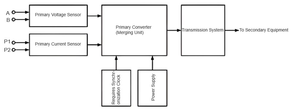
Electronic voltage transformers leverage electromagnetic induction and high-precision electronic measurement to convert high-voltage signals in power systems to low-voltage ones. Typically comprising a primary sensor, secondary conversion circuit, and signal processing unit: the primary sensor transforms high-voltage signals into weak current/voltage proportional to the primary voltage; the secondary circuit further converts these to standard digital/analog signals; the processing unit filters, amplifies, and calibrates signals to enhance measurement accuracy and stability. They can measure voltage, current, and power of a single circuit (as shown in Figure 1), or voltage/current of single/multiple circuits.
1.3 Analysis of Electromagnetic Interference & Sensitivity
Electronic voltage transformers are subject to electromagnetic interference from other electrical equipment (e.g., lightning impulses, transient overvoltages from switch operations), degrading measurement performance (e.g., increased errors, unstable readings).
2 Analysis of Electromagnetic Compatibility Performance Tests for Electronic Voltage Transformers(EVT)
2.1 Test Content and Evaluation Criteria
The electromagnetic compatibility performance test of an EVT is a critical step to ensure its stable and accurate operation in actual working environments. The test focuses on evaluating the EVT’s anti-interference capability and its performance under various electromagnetic disturbances. Evaluation criteria are divided into Grade A and Grade B based on the severity of test results:
Grade A: Maintains normal performance within the accuracy specification limits. The evaluation requires that when the EVT is subjected to electromagnetic disturbances, its measurement accuracy must stay within the specified limits. This ensures the output voltage signal matches the actual value and does not disrupt the normal monitoring and control of the power system.
Grade B: Allows temporary degradation of measurement performance unrelated to protection functions. The criteria permit temporary declines in measurement performance under electromagnetic disturbances, provided they do not affect the normal operation of protection functions or cause device reset/restart. The output voltage must be controlled within 500 V to avoid unnecessary interference or damage to the power system.
2.2 Conducted Interference Tests
Conducted interference refers to electromagnetic disturbances transmitted via conductive paths (e.g., wires, metal pipes). For EVTs, conducted interference is a major challenge.
Electrical Fast Transient/Burst (EFT/B) Test: Simulates transient disturbances from inductive loads (e.g., relays, contactors) during switching, which typically have wide frequency spectra and can disrupt EVT operation. The test applies a series of fast transient bursts to the EVT, observing the stability and accuracy of its output voltage signal to assess anti-interference capability.
Surge (Impulse) Immunity Test: Simulates transient overvoltages/currents from switch operations, lightning strikes, etc. These events carry high energy and short durations, severely impacting the EVT’s insulation and measurement accuracy. The test applies surge voltages to the EVT to verify its ability to withstand disturbances without damage or performance degradation.
2.3 Radiated Interference Tests
Power Frequency Magnetic Field Immunity Test: Evaluates the EVT’s performance in power frequency magnetic field environments. By applying a controlled power frequency magnetic field, the test observes the stability and accuracy of the output voltage signal to assess anti-interference capability.
Damped Oscillatory Magnetic Field Immunity Test: Simulates damped oscillatory magnetic fields generated when isolating switches in high-voltage substations operate on high-voltage busbars. These fields have fast decay rates and high frequencies, potentially disrupting EVT measurement accuracy. The test applies damped oscillatory magnetic fields to check if the EVT maintains stable measurement performance.
Pulse Magnetic Field Immunity Test: Simulates pulse magnetic fields from lightning strikes on buildings or other metal structures. These fields have fast rise times and high peak intensities, threatening the EVT’s insulation and measurement accuracy. The test applies pulse magnetic fields to verify the EVT’s ability to withstand disturbances without damage or performance degradation.
Radio Frequency Radiation Electromagnetic Field Immunity Test: Evaluates the EVT’s performance in radio frequency (RF) radiation environments (e.g., industrial electromagnetic sources, radio broadcasts, mobile communication base stations). By applying controlled RF radiation fields, the test observes the stability and accuracy of the output voltage signal to assess anti-interference capability.
3 Design Principles for Electromagnetic Compatibility of Electronic Voltage Transformers
3.1 Circuit Design Principles
Floating Ground Design: In circuit design, use floating ground technology to insulate signal lines from the chassis. This prevents interference currents on the chassis from directly coupling into the signal circuit, reducing noise interference and improving signal accuracy and stability.
Rational Wiring Layout: Properly arrange power lines, ground lines, and various signal lines—this is key to minimizing coupling interference. In EVT circuit design, ensure minimal coupling between lines. Methods like layered wiring and orthogonal routing (to avoid parallel runs) reduce electromagnetic induction and capacitive coupling.
Filter Capacitor Design: Implement filter capacitors at the power input of modules to suppress interference signals entering via the power supply. Select capacitors based on parameters like capacitance, voltage rating, and frequency characteristics to effectively filter high-frequency noise and interference from the power source.
Low-Level Logic Design: Avoid unnecessary high logic levels to reduce circuit power consumption and high-frequency interference. In EVT circuit design, prioritize low-level logic devices (e.g., 3.3 V devices) to minimize high-frequency noise emission and reception.
Rise/Fall Time Control: Choose the slowest allowable rise and fall times (within circuit function limits) to avoid generating unnecessary high-frequency components. This helps reduce high-frequency noise in the circuit and improves signal stability and accuracy.
3.2 Internal Structure Design Principles
Fully Enclosed Shielding Structure: Use a fully enclosed shield for the chassis, ensuring good contact between all surfaces and proper grounding. This effectively blocks external electromagnetic field interference, protecting internal electronic circuits from external disturbances.
Minimize Exposed Wiring Length: Keep all exposed wires inside the chassis as short as possible to reduce electromagnetic radiation and coupling interference. In EVT internal design, optimize component layout and placement to minimize exposed wire lengths.
Cable Grouping and Bundling: Group wires by signal type (e.g., separate digital and analog lines) and maintain appropriate spacing between groups. This reduces crosstalk between wires, improving signal clarity and accuracy.
Conductive Adhesive Bonding: Use conductive adhesive at all chassis interface joints to ensure good electrical connection and shielding effectiveness. This lowers contact resistance and enhances the shield’s performance.
4 Strategies for Improving Electromagnetic Compatibility Performance of Electronic Voltage Transformers
4.1 Anti - interference Design of Power Port
4.1.1 Install Power Filters
A power filter is an effective electromagnetic interference suppression device that can filter out high - frequency noise and transient pulses in the power supply, ensuring the purity of the power input. When selecting a power filter, choose the appropriate filter model and specification according to the rated power and working environment of the EVT, and ensure that the filter is installed close to the power inlet for the best filtering effect.
4.1.2 Adopt Redundant Power Supply Design
To improve the power supply reliability of the EVT, a redundant power supply design is adopted, that is, two or more power modules are configured. When one power module fails, other power modules can quickly take over the power supply task to ensure the normal operation of the EVT. This not only improves the anti - interference ability of the EVT but also enhances its overall stability.
4.1.3 Strengthen Shielding and Grounding of Power Lines
Power lines are one of the important paths for electromagnetic interference propagation. To reduce electromagnetic interference on power lines, shielded cables are used to wrap the power lines in a metal shielding layer, reducing the radiation and coupling of electromagnetic waves. At the same time, ensure good grounding of the power lines, guiding the interference current into the ground to avoid damage to the EVT.
4.2 Electrostatic Discharge Protection of Signal Ports
4.2.1 Install Transient Disturbance Absorption Components
Transient disturbance absorption components, such as Transient Voltage Suppressors (TVS) and varistors, can quickly absorb the discharge energy during electrostatic discharge and control the voltage within a safe level, protecting the internal electronic components of the EVT from damage. When selecting transient disturbance absorption components, choose the appropriate component model and specification according to the signal characteristics and working environment of the EVT.
4.2.2 Adopt Differential Signal Transmission Method
The differential signal transmission method can effectively resist common - mode interference and improve the anti - interference ability of the signal. In the signal port design of the EVT, the differential signal transmission method is adopted, dividing the signal into positive and negative channels for transmission. Effective information is extracted by comparing the signal differences between the two channels, which not only improves the signal transmission quality but also reduces the interference of electrostatic discharge on the EVT.
4.3 Optimization of Chassis Shielding Performance
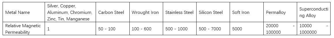
4.3.1 Select Materials with High Magnetic Permeability
The material selection of the chassis is crucial for the shielding effect. To improve the magnetic field shielding ability of the chassis, materials with high magnetic permeability, such as iron plates, are selected, which can effectively absorb and disperse magnetic field energy and reduce the interference of the magnetic field on the inside of the EVT. The relative magnetic permeability of metals is shown in Table 1.
4.3.2 Optimize Chassis Structure Design
The structural design of the chassis is also an important factor affecting the shielding effect. In the chassis design of the EVT, a fully enclosed shielding structure is adopted to ensure good contact and grounding between various surfaces.
4.3.3 Strengthen Chassis Grounding Treatment
The grounding treatment of the chassis is crucial for the shielding effect. In the chassis design of the EVT, it is necessary to ensure a good grounding connection between the chassis and the ground, guiding the interference current into the ground.
They also emit interference like high-frequency harmonics and electromagnetic radiation, impacting other devices. Designing them requires addressing these interference and sensitivity challenges with suppression and protection measures.
5 Conclusion
This paper conducts in - depth research and design on the electromagnetic compatibility performance of electronic voltage transformers. A series of measures are proposed, including circuit design principles, internal structure design principles, and electromagnetic compatibility performance improvement strategies. The aim is to enhance the anti - interference ability and stability of EVT in complex electromagnetic environments, ensure that it can accurately and reliably measure voltage signals in power systems, and provide strong guarantee for the safe and stable operation of power systems.