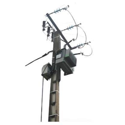
In modern power systems, DC electronic current transformers play a crucial role. They are not only used for high-precision current measurement but also serve as key tools for grid optimization, fault detection, and energy management. With the rapid development of high-voltage direct current (HVDC) transmission technology and its widespread deployment globally, the performance requirements for DC current transformers have become increasingly stringent, especially in terms of measurement accuracy and system compatibility. Therefore, the calibration technology of DC electronic current transformers has become the key to ensuring the safe, stable, and efficient operation of power systems.
1 Analysis of Calibration Technology for DC Electronic Current Transformers
1.1 Basic Principles of Calibration
The calibration of DC electronic current transformers is based on the principle of the magnetic-modulation DC current comparator and optical fiber digital synchronization technology. Among them, the magnetic-modulation DC current comparator uses magnetic-modulation technology to measure the magnitude of DC current. This technology relies on the influence of the magnetic field generated by the current on the magnetic properties of the iron core. In practical applications, when the current flows through the main conductor, it magnetizes the surrounding iron core. The magnetized iron core affects the current in a secondary coil through its changes, and this influence can be used as the basis for measuring the magnitude of the current in the main conductor.
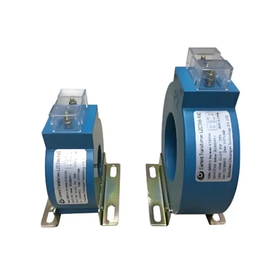
1.2 Composition of the Calibration System
The calibration system for DC electronic current transformers is mainly composed of a DC current source, the connection and synchronous configuration of the standard device and the device under test, and a high-precision data acquisition unit. The design and function of each part play a decisive role in the accuracy and reliability of the calibration process.
1.3 Calibration Methods
In the calibration process of DC electronic current transformers, the selection of calibration methods plays a decisive role in the accuracy and reliability of the measurement results. On-site calibration and laboratory calibration each have unique advantages and disadvantages. The high-accuracy digital direct measurement method provides an efficient calibration means. The calibration methods for analog and digital outputs are specifically adjusted for current transformers of different output types to adapt to various application scenarios.
(1) Comparison between On-site Calibration and Laboratory Calibration
There are significant differences between the two in terms of methods and environments:
(2) High-accuracy Digital Direct Measurement Method
With the help of high-precision digital measurement equipment, the output of the current transformer is directly read and compared with the known standard value, so that the calibration result can be obtained quickly and efficiently, and the error in intermediate links is reduced.
(3) Calibration Methods for Analog and Digital Outputs
The advantage of this method lies in fully considering the output characteristics of different types of current transformers:
2 Challenges and Countermeasures in Applying DC Electronic Current Transformer Calibration Technology
2.1 On - site Anti - interference
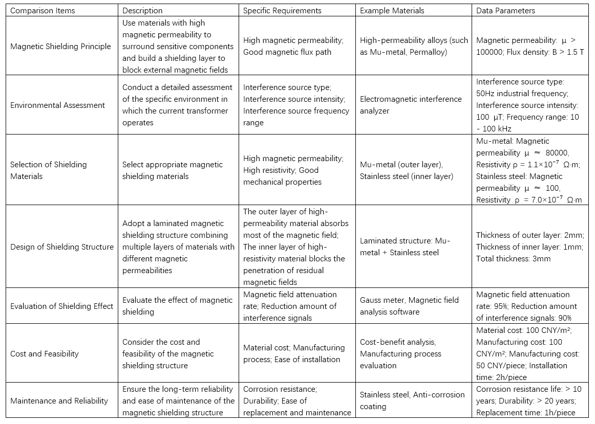
When applying DC electronic current transformer calibration on - site, severe electromagnetic interference arises. It stems from the high - voltage grid’s electromagnetic environment, including radiation from cables/equipment and system - generated noise. Such interference impacts measurement accuracy, causing calibration data deviations in HVDC systems and even damaging components. It brings both instant errors and long - term stability/reliability issues.
To tackle this, optimizing the magnetic shielding structure is key. The principle is using high - permeability materials to build a shielding layer around sensitive parts, blocking external magnetic fields. When designing, assess the actual environment (interference type, intensity, frequency) as these affect shielding effectiveness. A laminated structure with multi - layer, different - permeability materials works better. For example, the outer layer uses high - permeability materials to absorb most magnetic fields, and the inner layer uses high - resistivity materials to block residual fields. Optimized magnetic shielding design data is in Table 1.
2.2 Digital Synchronization Precision
In DC electronic current transformer calibration, synchronization precision is critical. Calibration often needs synchronizing multiple devices/data sources in scattered locations. Data precision/reliability depends on time synchronization; small deviations cause inaccuracies, affecting power system efficiency/safety. Selecting/optimizing synchronization tech and comparing optical fiber & GPS synchronization are vital.
In selecting/optimizing, the challenge is controlling complex power environments and wide geographical distributions for accurate synchronization. In strong - interference environments, traditional methods fail. Solutions include introducing IEEE1588 Precision Time Protocol and using precise time - stamping/modern communication for synchronization.
Optical fiber synchronization, with high speed and anti - interference, suits high - precision scenarios (e.g., data centers). It’s unaffected by electromagnetic interference, ensuring signal purity, but has high deployment costs. GPS synchronization is cost - effective, covers wide areas, and fits scattered networks. It uses satellite signals for time stamps but is less stable under severe interference. Synchronization precision comparison under different interferences is in Figure 1.
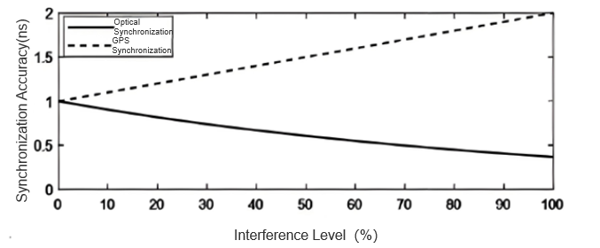
To address these challenges, select appropriate synchronization tech based on application environment and calibration needs. Prioritize fiber optic sync for low - EMI, high - precision scenarios. For geographically dispersed power networks, consider GPS sync and optimize receiver placement to reduce signal interference. Combining both to add redundancy also boosts sync precision and system reliability.
3 Conclusion
In conclusion, by conducting in - depth research on the calibration technology of DC electronic current transformers and their applications, it is not only of great significance for improving the performance and reliability of current transformers, but also a key factor in driving technological innovation and sustainable development of power systems. In the future, while continuing to optimize the calibration technology, attention should also be paid to the performance of these technologies in practical applications to ensure that they can meet the high - standard requirements of modern power grids.