
Systema GIS 500 kV stationis hydroelectricae Lianghekou constat ex circuit-breakeribus, disconnectoribus, earthing switchibus, bus-pipibus, current transformeribus (CTs), potential transformeribus (PTs), arrestoribus, et ceteris. Habet in totum duodecim circuit-breaker bays, adoptans structuram internam et dispositionem "Z"-formam, cum sex lineis introductis et duabus lineis emissis, utentes schemata wiring 4/3 et 3/2. Ut ad accessum projecti photovoltaici Kela in primo phase projecti complementari hydropv-heliopv stationis hydroelectricae Lianghekou, additus est novus outgoing-line bay (tertius outgoing-line bay) ad stationem hydroelectricam Lianghekou.
String 3/2 ubi sunt linea introducta No. 1 et No. 2 expansus est ad string 4/3. Bay originaliter reservatus pro accessu stationis hydroelectricae Yagen-nivis-1 mutatus est ad bay accessus venti-et-photovoltaici, et equipment in outgoing-line yard expansum est consequenter. Interficies inter expansum equipment GIS et iam commissionatum equipment GIS est ad disconnectores 50132 et 50122 et associatas gas compartments. Antequam incipiantur operatio expansionis GIS, ab latere Unitatis 1, power plant responsabilis est pro switching operatione disconnectoris 50122 et circuit-breaker 50122. Post completionem, notificat departmentum projecti quod operatio half-voltage reduction in gas compartment ubi est disconnector 50122 posse incipere. Ab latere Unitatis 2, power plant Lianghekou responsabilis est pro switching operatione disconnectoris 50132 et shutdown operatione Unitatis 2. Post completionem, notificat installation unit quod operatio half-voltage reduction in gas compartment ubi est disconnector 50132 posse incipere. Post completionem expansionis, installation unit responsabilis est pro restituendo pressionem gas in disconnectores 50132 et 50122 et associatas gas compartments.
Periodus constructionis pro modificatione et expansione tertii outgoing-line bay stationis hydroelectricae Lianghekou est tantum 30 dies. In his 30 diebus, oportet removeri existentia bus-pipes et instaurari et testari novi circuit breakers, CTs, et PTs in area operationis. Periodus constructionis est stricta, et pericula securitatis alta. Praeterea, in processu installationis equipment, elevatio restricta est, et non potest completari installation equipment per methodos elevationis consuetas.
Analyse Difficultatum Constructionis
Installation Novi Equipment GIS
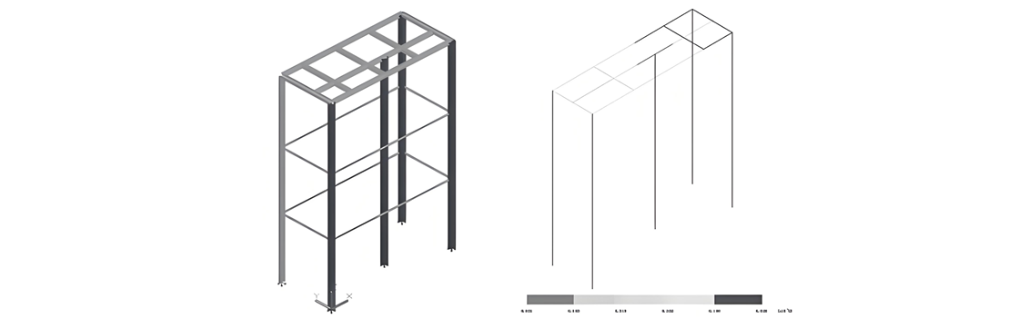
Interficies inter noviter installatum equipment GIS et iam commissionatum equipment GIS est ad disconnectores 50132 et 50122 et associatas gas compartments. Quando instauratur novus circuit breaker, oportet removeri connecting bus-pipes et supports inter 50132 et 50122, causans CTs et PTs supra disconnector 50132 suspendi, et support temporarius est difficilior. Praeterea, quando instauratur B-phase PT noviter additi disconnectoris 50131, obstructus est a live busbar supra, prohibens usu normali GIS bridge crane pro elevatione, resultans in difficultate installationis comparativae altiore.
Operationes in Area Operationis
Quando modificatio et expansio constructionis tertii outgoing-line bay geritur, equipment in GIS room et outgoing-line yard stationis hydroelectricae Lianghekou iam commissionatum est et vivit. Modificatio et expansio constructionis requirit removendum partium vivorum et commissionatorum equipment et operationes elevationis in vicinitate, praebens pericula securitatis significativa.
Preparationes Constructionis
Preparatio Listae Managementis Totius Ambitus
Dato tempore constructionis stricto et onere laboris gravi tertii outgoing-line bay, et considerante constructionem in area operationis power plant, ut assequatur progressum constructionis suavem, dominus, supervisor, power plant, manufactura equipment, et alii pariter discutiunt et preparant listam managementis totius ambitus, et requirunt omnes partes ad implendum suas responsabilitates stricto more secundum requisitiones listae. Lista totius ambitus dividitur in sequentes sex sectiones:
Planus Interruptionis Potentiae
Omnes partes discutiunt et enumerant taskos quae requirunt applicationes ad grid potentiae et dispatching, sicut interruptiones grid et testes grid-related in processu constructionis. Installation unit applicat ad power plant una septimana ante, et production department power plant applicat ad dispatching. Planus interruptionis clare definit nomen principale equipment quod interruptum est, tempora initii et finis interruptionis, contentum principale operis, et status desideratus equipment interrupti.
Planus Constructionis et Commissionis
Installation unit refinet planum progressus constructionis et commissionis secundum planum interruptionis et totum periodum constructionis, requirens refinement ad unicam operationem et clarificans tempora initii et finis unicuique operationi. Installation unit determinat human resources investitas in unicam operationem secundum planum constructionis et commissionis, et coordinate rationaliter human resources. Conventus post meridiem cotidie tenetur ad corrigendum deviationes in executione plani constructionis, assequens ut taski compleantur in eodem die.
Listam Emissionis Ticketorum et Planus
Ut assequatur operationem normalem in area operationis, omnes partes pariter preparant listam emissionis ticketorum et planum. Postquam listam emissionis ticketorum completur, confirmatur a operation department domini power plant. Operation department familiarizatur et praeparat operation tickets ante tempus. Installation unit potest tantum incipere operationem post obtinendum ticketa a operation department power plant secundum listam emissionis ticketorum. Emitting ticketis, contact person power plant includitur in membris team operationis. Listam emissionis ticketorum clare definit nomen emissionis, contentum operationis, person-in-charge operationis ticketorum et informationem contactus, tempus operationis, et contact person pro emissione ticketorum in power plant.
Listam Schematorum Installationis et Commissionis
Cum reconstructio et expansio involvent connectionem viva partium secondary cables ad systema operationis power plant, quod requirit operationem maintenance department power plant, omnes partes conveniunt ut maintenance department power plant praeparat schemam cooperationis pro reconstructione et expansione tertii bay, et installation unit praeparat schemata constructionis, commissionis, et testorum pro reconstructione et expansione. Listam clare definit nomen schematis, departmentum responsabile, tempus completionis primae draft, et tempus completionis ultimae draft.
Planus Aditus Personarum et Equipment
Installation unit enumerat tempora specifica aditus variarum typorum operariorum, regular testers, high-voltage testers, mobile cranes, forklifts, trucks, et aliarum personarum et equipment, et clarificat personas responsabiles. Supervisor et dominus faciunt assessments secundum schedule ut urgant installation unit ad assequendum ut personae et equipment ingrediantur locum in tempore et ut omnes resourses sint sufficienter praeparatae.
Planus Supply Materialium et Equipment
Installation unit enumerat planum aditus equipment et materialium supply Party B, et dominus enumerat planum aditus equipment et materialium supply Party A. Omnes partes sequuntur et implementant secundum planos aditus equipment et materialium ut assequantur quod equipment et materialia adveniant in tempore. Planus categorice enumerat nomen equipment, tempus supply, personam responsabilem, manufacturam, et alia informationem.
Preparationes Technicae
Confirmare cum power plant quod switching operationes equipment GIS completatae sunt, measures securitatis in loco sunt, et conditiones constructionis satisfactae sunt.
Measurement and Layout: Based on the GIS installation layout diagram and combined with the installation elevation of the outlet bushing, review the elevation coordinate points for GIS equipment installation, measure, mark, and record the installation positions.
Operarii debent mutare in work shoes et vestire purification suits quando ingrediuntur aream installationis. Work shoes et purification suits non permittuntur ad vestiendos extra aream installationis. Alii personae debent vestire shoe covers quando ingrediuntur aream installationis.
Organize all construction workers to understand the layout characteristics of the equipment in the entire expanded bay and get familiar with the installation process and process requirements, based on relevant drawings and manufacturer's materials.
Invite the manufacturer's and designer's on-site technicians and the supervision engineer to conduct a technical disclosure for all construction workers, so as to understand the design intent and the manufacturing plant's process characteristics, and correctly master the usage methods of professional tools.
Prepare all kinds of records, inspection forms, and process cards required during the installation and commissioning processes.
Isolation between Construction Area and Operating Area
Before equipment installation, use retractable fences to reasonably plan the construction site, demarcating the construction area, operating area, isolation area (the side against the mountain for the main transformer incoming line of Unit 1, 5011 circuit breaker, and 5012 circuit breaker), equipment and material storage area, construction passage, and operating passage. For the secondary switchboards below the outlet branch busbars in the construction area, adopt hard isolation protection. Use scaffolding pipes to erect a protective shed and lay wooden boards on the top.
Inspection of Arrived Equipment and Materials
The following items are mainly inspected during the arrival acceptance of GIS equipment:
Before unpacking, check whether the packaging is damaged and whether there is any collision, damage, or loss during transportation.
Check the integrity and correctness of the delivered equipment according to the order and delivery documents.
Check whether the paint, anti-rust layer, color, and quality on the equipment surface meet the requirements.
Check whether the text and data on the nameplate are correct.
Carefully check against the packing list whether the product accessories, spare parts, installation supplies, and special tools are complete, and whether there are any signs of damage, deformation, or rust.
Check whether the bushings have any deformation, moisture, cracks, or defects.
Check whether the factory certificates, relevant drawings, materials, and documents are complete.
Check whether the value of the three-dimensional anti-tampering instrument exceeds 3 g.
Equipment Installation
Gas Recovery and Pressure Reduction
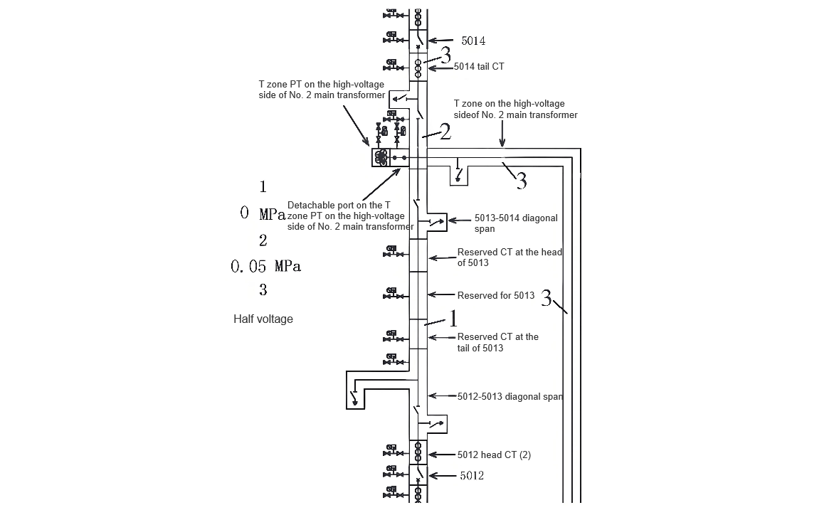
Before equipment installation, reduce the pressure to half at the detachable break points of the 5014 terminal CT, the high-voltage side T-zone PT of the No. 2 main transformer, the high-voltage side T-zone of the No. 2 main transformer, and the 5012 initial CT, as well as the high-voltage side T-zone PT of the No. 2 main transformer (see Part 3 in the figure for details); recover the gas from the 5013-5014 diagonal span to the 5012 initial CT (see Part 1 in the figure for details); retain a slight positive pressure of 0.05 MPa during gas recovery in the gas chamber from the 5014 terminal CT to the 5013-5014 diagonal span (see the colored block in Part 2 of the figure). The gas recovery and pressure reduction are shown in Figure 2.
Disassembly and Support of Bus-pipes
After gas recovery and pressure reduction are completed, before the circuit breaker is positioned, first remove the maintenance platform, and then remove the "L"-shaped bus-pipe of 5013. When removing the "L"-shaped bus-pipe, use a gantry to hoist and fix the PT, CT, disconnector, 5013-5014 diagonal bus-pipe, and 5012-5013 diagonal bus-pipe in this area with the tooling.
Foundation Point-setting and Equipment Positioning
According to the manufacturer's drawings, design drawings, and the installation status of existing equipment, use an ink line box to mark out and identify the (X, Y) center lines of the equipment. Measure and fix the relative positions of the equipment with a steel tape measure according to the center line of the B-phase of the incoming and outgoing lines; at the same time, mark the elevation points of the equipment to determine the installation elevation of the equipment.
Install the equipment in place according to the design drawings, and review the centers and elevations of all equipment to ensure the correct installation positions.
After the GIS room equipment is transported to the on-site hoisting hole in sequence, it is hoisted to the installation position inside the GIS room by a 10-t single-girder crane. During hoisting, the "Ten No-Hoisting Rules" are strictly implemented. Each component must be test-hoisted for three times of lifting and lowering before hoisting. The hoisting area should try to avoid the operating area. The equipment must enter the site in strict accordance with the installation sequence to avoid the accumulation and congestion of equipment on-site, which may affect the installation progress. GIS equipment must be hoisted with the special lifting tools provided by the manufacturer, and the equipment should not be damaged during handling.
When the equipment of a unit is initially positioned, first position the circuit breaker, and then position other equipment. Since the diagonal-spanning bus-pipe between 5013 and 5014 has not been removed, the 10-t bridge crane in the GIS room [3-5] cannot directly hoist the circuit breaker into position. Therefore, in this installation, a manual hydraulic forklift is used to transport the circuit breaker to the installation position, and then the positioning adjustment is carried out. Ensure that the center and elevation of the circuit breaker meet the design requirements.
Refer to the elevation of existing equipment during equipment installation. Before installation or connection, the equipment should be adjusted to be straight and level. Forcing, prying, or hard-aligning the equipment manually is strictly prohibited.
Tighten all connecting bolts with a torque wrench according to the specified torque.
Installation of Voltage Transformers
Since the B-phase voltage transformer behind the 5013 circuit breaker (weighing about 1 t and with an installation height of about 6 m) is installed directly below the B-phase of Bus Ⅱ, and Bus Ⅱ is in a live-operation state, the 10-t bridge crane in the GIS room cannot directly hoist the voltage transformer into position. After consulting with multiple parties, it is decided to introduce an industrial forklift. The forklift has a rated load capacity of 1.5 t and a maximum lifting height of 7 m, which meets the on-site requirements and can move flexibly on-site.
Before installation, check whether the internal pressure value of the transformer is the original inflation pressure and conduct routine tests.
Clean the electrical contact surfaces on the sealing surface and the connecting flange with lint-free paper dipped in anhydrous alcohol.
During the installation of the voltage transformer, adjust the verticality and levelness through the screws on the base to ensure a proper connection with the bus-connection surface and complete the flange connection.
The conductor inside the detachable port at the lower end of the newly-added voltage transformer should be installed after the withstand voltage test is completed.
Conclusion
During the modification and expansion construction of the third bay of the 500 kV GIS at Lianghekou Hydropower Station, faced with unfavorable factors such as a tight construction schedule, construction in the operating area, and restricted lifting, through a series of measures including formulating a full-scope management list, manufacturing special tooling, and introducing industrial forklifts, the smooth progress of the modification and expansion construction of the third bay was ultimately ensured. This shortened the construction period, saved costs, and guaranteed safety and quality. It has set a precedent for in-depth cooperation between operations in the 500 kV GIS operating area and the power plant, and has certain reference and promoting significance for similar modification and expansion projects.


