HV Circuit Breaker Testing: Methods & Safety Tips

High-Voltage Circuit Breaker Characteristic Tests: Methods and Precautions
High-voltage circuit breaker characteristic tests mainly include mechanical performance testing, loop resistance measurement, anti-pumping function verification, and non-full-phase protection testing. Below are the detailed test procedures and key precautions.
1. Pre-Test Preparation
1.1 Technical Documentation Review
Review the operating mechanism manual to understand its structure, working principle, and technical parameters (e.g., opening/closing time, synchronization requirements, contact travel). Collect installation records, maintenance logs, and previous test reports to analyze historical anomalies.
1.2 Equipment Preparation
Prepare a circuit breaker mechanical characteristics tester, loop resistance tester, relay protection tester, etc. Ensure all instruments are calibrated and meet required accuracy standards.
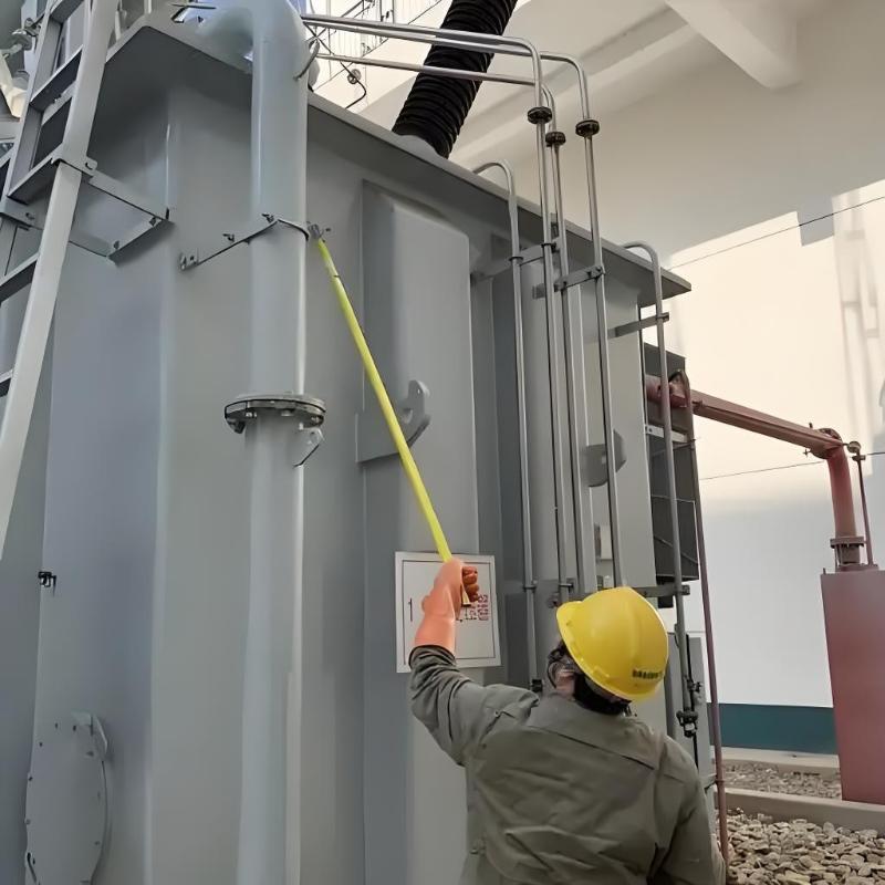
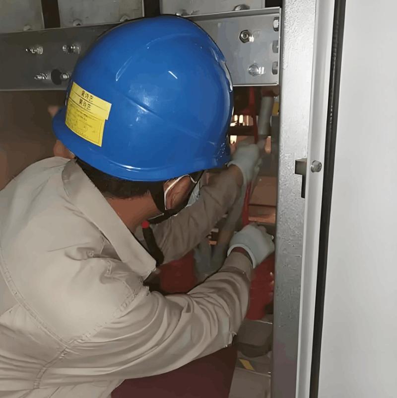
1.3 Safety Measures
Disconnect control and energy storage power before testing; release stored energy in the operating mechanism.
Personnel must wear insulated gloves, safety goggles, and other protective gear. Set up warning signs in the test area.
Ensure proper grounding of test equipment to prevent risks from induced voltage or leakage current.
2. Mechanical Characteristics Test
2.1 Opening/Closing Time Measurement
Install displacement sensors on the moving contacts or use auxiliary contacts to capture motion signals. Operate the breaker at rated control voltage and rated operating pressure. The tester automatically records opening and closing times. Perform multiple measurements (at least 3), take the average, and compare with manufacturer specifications.
2.2 Synchronization Check
Measure the time difference between the fastest and slowest phase during opening/closing. Phase-to-phase synchronization error should generally not exceed 3–5ms; inter-pole synchronization within the same phase must be even smaller. If out of tolerance, check consistency in transmission link lengths, positioning, or hydraulic system parameters.
2.3 Contact Travel and Overtravel Measurement
Use the tester’s stroke measurement function or indirectly calculate travel and overtravel from linkage displacement. Values must comply with product standards. Adjust transmission components if deviations exist.
2.4 Opening/Closing Speed Measurement
Measure speed over a defined segment near the instant of contact separation (just-open) and contact touch (just-closed). Calculate just-open speed, just-closed speed, and maximum speed. Results must fall within specified limits. Abnormal values may indicate issues with hydraulic pressure, spring condition, or drive components.
2.5 Closing Bounce Time Measurement (Applicable to Vacuum Circuit Breakers)
Measure the time interval between initial and final contact engagement during closing. Typically required to be ≤2ms. Excessive bounce may impair arc interruption; inspect contact pressure and spring performance.

3. Loop Resistance Test
3.1 Define Conductive Path
Identify key components of the conductive path: line terminals, load terminals, and contact system.
3.2 Clean Test Points
Remove oxidation and dirt from contact surfaces using sandpaper or cleaning tools to ensure good electrical contact.
3.3 Measure Loop Resistance
Use a micro-ohmmeter to pass a constant DC current (e.g., 100A or 200A) through the main circuit and measure voltage drop. Calculate resistance accordingly. Typical values range from tens to hundreds of micro-ohms. Exceeding limits indicates poor contact, loose bolts, or deteriorated contacts requiring inspection.
4. Anti-Pumping (Trip-Lockout) Function Test
4.1 Test Method
With the breaker closed, simultaneously apply close and trip commands. The breaker should trip once and remain locked out—no re-closing.
With the breaker open, apply close and trip commands together. It should close then immediately trip, ending in the open position.
4.2 Function Verification
If only one trip occurs and the anti-pumping relay reliably locks the closing circuit, the function is normal. If repeated operation ("pumping") occurs or the relay fails to actuate, inspect the anti-pumping circuit, including relay, contacts, and wiring integrity.
5. Post-Test Procedures
5.1 Data Recording and Analysis
Compare test results with technical specifications. Investigate root causes for any out-of-tolerance data and perform adjustments or repairs as needed.
5.2 Restore Equipment
After testing, return the breaker to its original state. Remove test leads and sensors. Confirm no abnormalities before returning to service.
6. Key Precautions
Prohibit unauthorized operation of the breaker or test equipment during testing to prevent misoperation or mechanical injury.
Securely install sensors to avoid affecting measurement accuracy.
For breakers with dual trip coils, separately test low-voltage tripping characteristics, trip time, and speed for each coil.
Perform insulation withstand (hi-pot) tests before and after characteristic tests to verify dielectric integrity.