Fast Insertion of Shunt Reactors
Purpose:
Shunt reactors are primarily used to compensate for the capacitance of long transmission lines, which can lead to overvoltages and reactive power issues. They provide a secondary benefit by reducing switching overvoltages when connected, but this is not typically the primary reason utilities install them. The main objectives of shunt reactors include:
Capacitance Compensation: Long transmission lines have significant capacitance, especially at Extra High Voltage (EHV) levels. This capacitance can cause overvoltages, particularly during light load conditions or when the line is open. Shunt reactors help mitigate these overvoltages by providing a reactive load that counteracts the capacitive effects.
Switching Overvoltage Reduction: While not the primary purpose, shunt reactors can also reduce switching overvoltages. When a circuit breaker opens or closes, transient overvoltages can occur. Shunt reactors can absorb some of these transients, thereby reducing the magnitude of the overvoltages.
Application:
Shunt reactors are typically installed at substations along long transmission lines, especially in EHV systems where the capacitance effect is more pronounced.
They are not usually added solely to reduce switching overvoltages because other measures (such as closing resistors or controlled closing) are more effective for this specific purpose.
Closing Resistors
Purpose:
Closing resistors are used to limit the voltage rise at the receiving end of a transmission line when it is energized. The primary goal is to keep the voltage within acceptable limits, typically around 2 per unit (p.u.), to prevent equipment damage and ensure system stability.
Operation:
When a transmission line is energized, a sudden surge of current can cause a significant voltage rise at the receiving end, leading to overvoltage conditions.
Closing resistors are temporarily connected in series with the circuit breaker during the closing operation. They limit the initial current surge and dampen any resulting transients, thus preventing the voltage from exceeding 2 p.u.
Once the transients have subsided, the resistors are bypassed, and the line operates normally.
Benefits:
Voltage Limitation: Keeps the receiving-end voltage within safe limits, protecting equipment and ensuring stable operation.
Transient Suppression: Reduces the magnitude of switching overvoltages, which can be particularly important in EHV systems.
Staggered Pole Closing
Principle:
Staggered pole closing involves closing the individual poles of a three-phase circuit breaker one-half cycle apart. The idea is to allow transients in the first phase to attenuate before the next phase is closed, thereby reducing the likelihood of severe overvoltages.
Operation:
In a three-phase system, each phase is closed sequentially, with a delay of half a cycle (10 ms at 50 Hz or 8.33 ms at 60 Hz) between each phase.
By staggering the closing, the transients generated by the first phase have time to decay before the next phase is energized. This reduces the cumulative effect of transients and minimizes the risk of overvoltage events.
Benefits:
Transient Attenuation: Allows transients from the first phase to dissipate before the next phase is closed, reducing the overall severity of overvoltages.
Simplified Implementation: Does not require complex control systems, making it a relatively simple and cost-effective method for mitigating overvoltages.
Line Terminal Arresters
Purpose:
Line terminal arresters are installed at the ends of transmission lines to protect against overvoltages caused by lightning strikes or switching operations. They limit the overvoltages at the points where they are installed to the protective level of the arrester.
Operation:
Arresters are designed to conduct excess energy away from the system when overvoltages exceed a certain threshold. They clamp the voltage to a safe level, preventing damage to equipment and ensuring the integrity of the transmission system.
Typically, arresters are placed at both ends of the transmission line (sending and receiving terminals). However, they only limit overvoltages at those specific locations and do not provide protection along the entire length of the line.
Benefits:
Overvoltage Protection: Effectively protects equipment at the line terminals from overvoltages caused by lightning or switching.
Targeted Protection: Provides focused protection at critical points in the system without the need for additional equipment along the entire line.
Controlled Closing
Principle:
Controlled closing is an advanced mitigation measure that uses a dynamic controller to analyze the differential voltage across the circuit breaker, predict future voltage minima, and close the breaker at the optimal moment to minimize overvoltages. The entire process must be completed within less than 0.5 seconds to be effective.
Operation:
A dynamic controller continuously monitors the voltage difference across the circuit breaker.
It identifies the minimum voltage points and predicts when future minima will occur.
The controller then closes the breaker at the predicted minimum voltage point, ensuring that the closing occurs during a low-voltage period and minimizing the risk of overvoltage.
This method requires fast and accurate control algorithms, as well as precise timing to ensure the breaker closes at the optimal moment.
Benefits:
Minimized Overvoltages: By closing the breaker at the optimal voltage point, controlled closing significantly reduces the magnitude of overvoltages.
Improved System Stability: Helps maintain system stability by preventing excessive voltage surges during line energization.
Advanced Technology: Offers a more sophisticated and effective solution compared to traditional methods like staggered pole closing or closing resistors.
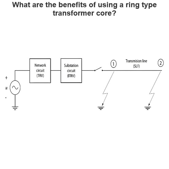
Overvoltage Profile in EHV Long Lines
The figure showing the overvoltage profile in an EHV long line demonstrates the effectiveness of various overvoltage limitation options. Each method has its own impact on the overvoltage levels, and the choice of method depends on the specific requirements of the system.
Fast Insertion of Shunt Reactors: Reduces overvoltages due to line capacitance and provides some reduction in switching overvoltages.
Closing Resistors: Limits the receiving-end voltage to 2 p.u., effectively controlling overvoltages during line energization.
Staggered Pole Closing: Reduces the cumulative effect of transients by allowing them to attenuate between phase closings.
Line Terminal Arresters: Protects the line terminals from overvoltages but does not provide protection along the entire line.
Controlled Closing: Minimizes overvoltages by closing the breaker at the optimal voltage point, offering the most effective control over transient overvoltages.
Each of these methods can be used individually or in combination to achieve the desired overvoltage mitigation in EHV long lines, depending on the system's specific needs and constraints.