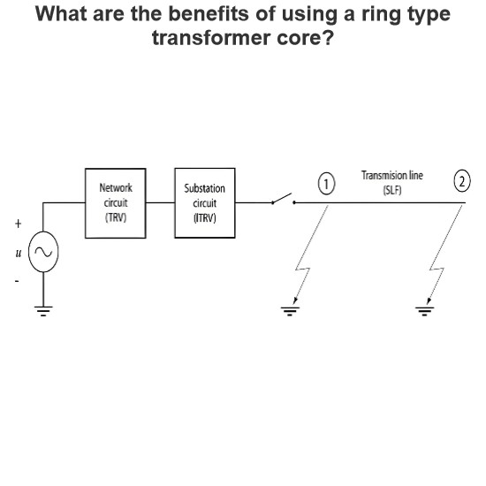
In analyzing transient phenomena caused by switching operations in linear systems, the principle of superposition is a powerful tool. By combining the steady-state solution that existed before the open-circuit operation with the transient responses induced by short-circuit voltage sources and open-circuit current sources, and considering the current injected through the switch contacts, a comprehensive description of the switching process can be obtained.
During an open-circuit operation, the current flowing through the switch terminals must become zero after the operation. Therefore, the current injected into the system must equal the current that was flowing through the switch terminals before the opening operation. As the switch contacts begin to separate, a transient recovery voltage (TRV) immediately develops across the contacts. The TRV appears immediately after the current reaches zero and typically lasts for milliseconds in real-world systems. In practical power systems, the characteristics of the TRV are crucial for the performance and reliability of circuit breakers.
A thorough understanding of the transient phenomena associated with circuit breaker operations in power systems can significantly improve testing practices and enhance the reliability of switching equipment. Standards specify recommended characteristic values for simulating TRV, which help engineers better predict and design the behavior of switching devices.
The following diagram illustrates the TRV at the circuit breaker terminals when interrupting current in very simple circuits. Each case results in different waveforms, depending on the nature of the circuit:
Resistive Load: For purely resistive loads, the current drops to zero quickly after the switching operation, resulting in a relatively smooth TRV waveform.
Inductive Load: For inductive loads, the voltage across the inductor reaches its maximum value when the current becomes zero. Since the inductor stores energy, which needs to be dissipated through other components (such as capacitors), oscillations occur. These oscillations are caused by the energy transfer between the inductor and the capacitor.
Capacitive Load: For capacitive loads, the current gradually decreases after the switching operation, while the voltage rises rapidly. The TRV waveform typically exhibits a fast-rising voltage pulse.

In power systems, the interruption of small currents can lead to phenomena known as current chopping and virtual chopping. These phenomena have significant impacts on the transient recovery voltage (TRV) and can result in overvoltage and reignition issues.
Normal Interruption: When the current is interrupted naturally at its zero crossing point, this is the ideal switching operation. In this case, the TRV typically remains within specified limits, and no overvoltage or reignition occurs.
Current Chopping: If the current is interrupted prematurely before it reaches zero, this phenomenon is called current chopping. The sudden interruption of current leads to the generation of transient overvoltages, which can cause high-frequency reignition. This type of abnormal interruption poses potential hazards to the circuit breaker and the system.
When a circuit breaker interrupts the current near its peak, the voltage almost instantly rises. If this overvoltage exceeds the dielectric strength specified for the circuit breaker, reignition occurs. When this process repeats multiple times, the voltage continues to rise rapidly due to high-frequency reignition. This high-frequency oscillation is controlled by the electrical parameters of the associated circuit, the circuit configuration, and the design of the circuit breaker, leading to a zero crossing before the actual power frequency current reaches zero.
Current Chopping: Occurs when the current is interrupted before it reaches zero, resulting in transient overvoltage and high-frequency reignition.
Virtual Chopping: Happens when the current is interrupted just before it reaches zero, although it is very close to zero. This can still cause minor overvoltage and reignition.
The following diagram compares the load-side voltage and TRV under two different scenarios:
Interruption at the Current Zero Point: In this case, the load-side voltage rises steadily, and the TRV remains within specified limits, ensuring normal system operation.
Interruption Before the Current Zero Point (Current Chopping): Here, the load-side voltage rises rapidly, and the TRV significantly increases, potentially leading to overvoltage and reignition. It is clear from this example that the second scenario is more severe.
To better understand the impact of current chopping, consider ignoring the effects of load-side losses. After the current is interrupted at the zero point, the energy stored on the load side is primarily in the capacitors, where the voltage reaches its maximum value. However, if the current is chopped before reaching zero, the energy in the capacitors cannot be fully dissipated, leading to a rapid voltage rise and subsequent overvoltage and reignition issues.

In the case of current chopping, the instability of the arc near the current zero point can lead to high-frequency transient currents flowing into adjacent network components. This high-frequency current overlays on the smaller power frequency current, which is effectively chopped to zero. Specifically:
Arc Instability Near Current Zero: As the current approaches zero, the arc may become unstable, generating high-frequency transient currents. These currents superimpose on the already small power frequency current, further complicating the system's transient response.
Impact of High-Frequency Transient Currents: The presence of high-frequency transient currents can cause overvoltage and reignition, especially in inductive loads. Due to the rapid changes in these currents, they can produce extremely high voltage peaks in a short time, posing a threat to the insulation materials in the system.
In the case of virtual chopping, the arc instability is exacerbated by oscillations with adjacent phases, leading to the generation of high-frequency currents even before the current reaches zero. Specifically:
Mechanism of Virtual Chopping: Virtual chopping typically occurs when the current is close to but has not yet reached zero. At this point, the arc may interact with oscillations from adjacent phases, resulting in high-frequency current generation. This further destabilizes the system and increases the risk of reignition.
Observed Phenomenon: Virtual chopping has been observed in gaseous arcs in air, SF6, and oil. Vacuum arcs are also highly sensitive to current chopping because the arc in a vacuum environment is more susceptible to external conditions, leading to increased instability.
The phenomena of chopping and reignition, along with associated high-frequency oscillatory overvoltages, are primarily attributed to the design of the circuit breaker. Specifically:
Design for High Fault Currents: Circuit breakers are typically designed to handle high fault currents. If the design focuses solely on the effective performance for high currents, it may also be equally effective for small currents, attempting to interrupt them before their natural zero crossing.
Adverse Consequences: This design approach can lead to current chopping and reignition, resulting in overvoltage and other undesirable effects. For example, overvoltage can damage the system's insulation, leading to equipment failure or shortened lifespan.
To effectively address both small and large currents, circuit breaker design should incorporate multiple features to ensure reliable performance under various conditions. Specific recommendations include:
Balancing Performance for Small and Large Currents: Circuit breaker design should consider both small and large currents, avoiding over-optimization for one type at the expense of the other. For instance, adjusting contact materials, arc extinguishing chamber design, and control strategies can help balance performance across different current levels.
Reducing High-Frequency Oscillations: The design should aim to minimize high-frequency oscillations, especially near the current zero point. This can be achieved by introducing appropriate damping elements or optimizing circuit parameters to suppress high-frequency transient currents.
Enhancing Insulation Performance: To handle potential overvoltages, the circuit breaker's insulation design should have sufficient dielectric strength. Selecting high-performance insulating materials and optimizing the insulation structure can ensure reliable insulation even under extreme conditions.