Withstand voltage test of high-voltage cables

Withstand voltage test is an insulation test, but it is a destructive test that can reveal insulation defects difficult to detect in non-destructive testing.
The test cycle for high-voltage cables is three years, and it must be conducted after non-destructive tests. In other words, the withstand voltage test is performed only after all non-destructive tests have been passed.

Most high-voltage cables used today are cross-linked polyethylene (XLPE) cables, which can have large cross-sections and cover a wide range of voltage levels. Therefore, it is expected that their application will become increasingly widespread.
This article uses the most common 10 kV high-voltage cable as an example. In fact, there is not much to elaborate—the test is simple and the method is similar to insulation testing, except that the test equipment is different.
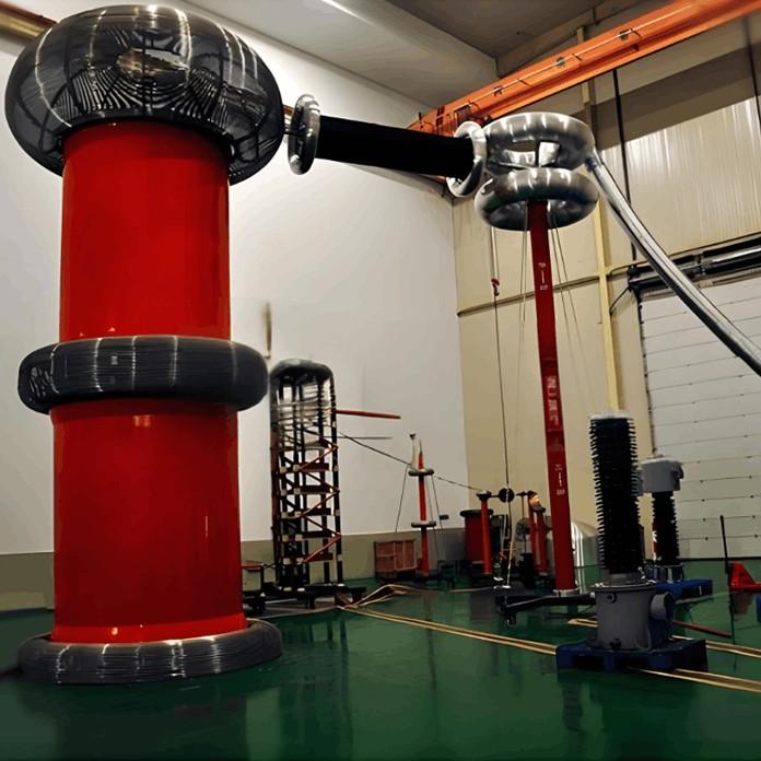
Measure insulation resistance using an insulation resistance tester (megger), while the withstand voltage test requires a series resonant test set.

The principle and wiring of series resonance testing are also very simple. It's not as if series resonance equipment is something particularly new, as it has been used for many years.
Series resonance is relatively easy to understand, and is specifically explained in fundamental electrical engineering courses. High-voltage cables are capacitive test objects, capable of storing electric charge during the voltage application process.
Therefore, regardless of whether a high-voltage cable is energized or not, never attempt to touch it by hand. Even if it's de-energized, the discharge from its capacitance alone can be quite dangerous!
Without personal experience, one should not make casual conclusions. Those who haven't experienced it should never try it lightly.
Since the test object is capacitive, an inductor is connected in series within the test circuit. Resonance is achieved by utilizing the principle that inductive reactance (XL) equals capacitive reactance (XC).
This resonance condition can be achieved either by adjusting the inductance value or by changing the power supply frequency. How do we adjust the inductance? Naturally, it is determined based on the capacitance, because XL must equal XC.
For a given cable, once the model and length (in meters) are known, the capacitance can be obtained from reference tables or provided by the cable manufacturer.
As for changing the power supply frequency, the classic formula f₀ = 1/(2π√LC) is used, where f₀ is the resonant frequency.
At the resonant frequency, XL = XC, and the voltages across the inductor and the test object's capacitance become equal. This voltage is Q times the source voltage, where Q is the quality factor, also known as the voltage magnification factor.
The Q value can be very high, reaching up to 120 (refer to specific equipment manuals for exact values). This significantly reduces the required power supply capacity, which is precisely why series resonance equipment has been widely adopted.
Ordinary series resonance equipment can typically provide an adjustable frequency range of 30–300 Hz, making it convenient to locate the resonance point.

Finally, let's discuss the test voltage. For 10 kV high-voltage cables, the preventive test voltage is selected as 2U₀, with a duration of 5 minutes. The test is considered passed if there is no discharge, no breakdown, no heating, no smoke, and no unusual odor.
There are two types of 10 kV cables: 6/10 kV and 8.7/15 kV. The appropriate test voltage must be selected according to the specific cable model.