Di şîstemê bîrkarîyê ya Çîn, şebê 6 kV, 10 kV, û 35 kV jî hîstenda ku li ser xwe rezhayêkê bi nav kirin da ku pênayek neutral nabe. Tarzê bîrkarîyê ya sernavên peyvên mînîk di şebê de hejmarên delta yên hatine sererast kirin, ku ne pênayek neutral nabe ji bo bikirina rîsistanên grounding. Wanî diga ku ewlekî single-phase ground fault da bikar îndera şebê bi pênayek neutral nabe, triangle ê voltage ê line-to-line werdê te symmetrical bibim, ku min imtixan bidin da ku karûbarên bikarhêner ê were bêdar be. Ji bilî, wanî diga ku amperajê capacitive wek e ku be (wenî 10 A), hînî ewlekî transient ground faults dikarin biguherînin, ku çêtir ast da ku bîrkarîyê baxbexandin û vêgirîna qeyb-bûnên bike.
Lê, bi derbas û parzûna çarçoveya bîrkarîyê, yekemîna wê rezhayêkê tê veşartî yên heyî ne. Di şebê bîrkarîyê ya modern urban de, pirkerdina cable circuits da amperajê capacitive wek e ku meheng be (wenî 10 A). Li vir navbera şertên wan, arcê ground dikare ne guherînin bêdar, ku hewce bike da ku wanî cihand be:
Guhertina û veguheztina ewlekî single-phase ground arc dikare overvoltages ê arc-ground bide ku amplitudes ê wan da ku 4U (wenî ku U ê peak phase voltage be) an jî zêde be, ku destpêkirin dikare dibe. Ew ê bêdilên bêdar bide ji bo insulation ê equipment ê bîrkarî, ku dikare bide da ku breakdown ê weak insulation points dibin, û lossên meheng bikin.
Arcing ê sustained dikare air ê surrounding ionize bikin, ku properties ê insulating ê wan bêdar bikin û pelanên phase-to-phase short circuits zêdebikin.
Ferroresonant overvoltages dikarin pêwend bikin, ku asayishan dikare transformers ê voltage û surge arresters biguherînin—wanî diga ku explosion ê arrester dibin. Wanî cihand dikare bêdilên bêdar bide ji bo integrity ê insulation ê equipment ê grid û threat bikin ji bo safe operation ê entire power system.
Bi ra'azeta wanî cihand û biafirandina current û voltage ê zero-sequence bêdar û reliable operation ê ground-fault protection, pênayek neutral artificial hewce ye da ku bikin, ta ku resistor ê grounding bikin connect bikin. Hesabda wanî need, development ê transformers ê grounding (commonly referred to as "grounding transformers" or "grounding units") pêwend bike. Transformer ê grounding pênayek neutral artificial bikin ji bo resistor ê grounding, ku resistance ê wan very low be (wenî 5 ohms).
Ji bilî, wanî electromagnetic characteristics ê transformer ê grounding, impedance ê high present dikare ji bo currents ê positive- û negative-sequence, ku only small excitation current dikare flow bikin ji bo windings ê wan. Ser her core limb, two winding sections în opposite directions dikare wound bikin. Wanî diga ku zero-sequence currents equal flow bikin ji bo windings ê wan, wan dikare impedance ê low present bikin, ku voltage drop ê minimal across ê windings under ê zero-sequence conditions bikin.
Specifically, during a ground fault, the winding carries positive-, negative-, and zero-sequence currents. It presents high impedance to positive- and negative-sequence currents but low impedance to zero-sequence current. This is because, within the same phase, the two windings are connected in series with opposite polarity; their induced electromotive forces are equal in magnitude but opposite in direction, effectively canceling each other out, thus presenting low impedance to zero-sequence current.
In many applications, grounding transformers are used solely to provide a neutral point with a small grounding resistor and do not supply any secondary load. Therefore, many grounding transformers are designed without a secondary winding. During normal grid operation, the grounding transformer operates essentially in a no-load state. However, during a fault, it carries fault current only for a short duration. In a low-resistance grounded system, when a single-phase ground fault occurs on the 10 kV side, highly sensitive zero-sequence protection quickly identifies and temporarily isolates the faulty feeder.
The grounding transformer is active only during the brief interval between fault occurrence and the operation of the feeder’s zero-sequence protection. During this time, zero-sequence current flows through the neutral grounding resistor and the grounding transformer, following the formula: I_R = U / (R₁ + R₂), where U is the system phase voltage, R₁ is the neutral grounding resistor, and R₂ is the additional resistance in the ground fault loop.
Based on the above analysis, the operational characteristics of a grounding transformer are: long-term no-load operation and short-term overload during faults.
In summary, a grounding transformer artificially creates a neutral point to connect a grounding resistor. During a ground fault, it exhibits high impedance to positive- and negative-sequence currents but low impedance to zero-sequence current, thereby ensuring reliable operation of ground-fault protection.
Currently, grounding transformers installed in substations serve two primary purposes:
Supplying low-voltage AC power for substation auxiliary use;
Creating an artificial neutral point on the 10 kV side, which, when combined with an arc suppression coil (Petersen coil), compensates for capacitive ground-fault current during 10 kV single-phase ground faults, thereby extinguishing the arc at the fault point. The principle is as follows:
Along the entire length of conductors in a three-phase power grid, capacitance exists both between phases and between each phase and ground. When the grid neutral is not solidly grounded, the capacitance to ground of the faulted phase becomes zero during a single-phase ground fault, while the voltages of the other two phases rise to √3 times the normal phase voltage. Although this increased voltage remains within the insulation design limits, it increases their capacitance to ground. The capacitive ground-fault current during a single-phase fault is approximately three times the normal per-phase capacitive current. When this current becomes large, it easily sustains intermittent arcs, exciting resonant oscillations in the grid’s inductive-capacitive circuit and generating overvoltages up to 2.5–3 times the phase voltage. The higher the grid voltage, the greater the risk from such overvoltages. Therefore, only systems below 60 kV may operate with an ungrounded neutral, as their single-phase capacitive ground-fault currents remain small. For higher-voltage systems, a grounding transformer must be used to connect the neutral point through impedance.
Ji bêkîna pêşpeyên transformatora sereke (bikarhêner 10 kV) ya birêvebirê bi delê delta an wye bikar an neytral nayê derbas kirin, û cûrên kapasitîfek yek parreya mezin bin, tune neytral nayê ji bo serkirina. Li vir dîtayî, transformatora serkirina bikar an jî bi qaniyayê neytral da dest pê kirin, ku hûn dikarin bi tîpêya arc suppression coil serkirin. Neytral artîfîsyal ê dike guherandina cûrên kapasitîfek û xerîdar kirina arc'ê—ev ûa rolê serekeya transformatoreya serkirina ye.
Di dema çalakiyeyê de, transformatora serkirina dike voltajê ya sê parreyê berhemî û tikandin cûrên excitation mezin nayê, dike çalakî bi behtirîna. Diferansê potensiyel ê di neytral û zeminê de sifir e (neglecting minor neutral displacement voltage from the arc suppression coil), û cûr nayê di tîpê de girêt. Ger, mînak, parra C li serkerdina serkirina re, voltajê zero-sequence (ji nistînin asimetrik) dike giranî ji bo tîpêya arc suppression coil ser zemin. Tîpê inductive current dikare ku cûrên ground-fault kapasitîfek kompensasyon bike, û xerîdar kirina arc—functionally identical to a standalone arc suppression coil.
Di salan dek, pirser misoperations van transformatoreya serkirina protection di 110 kV birêvebiran de li gorî cih û herêmekê, dike nivîsina stabilitêta grid. Ji bo dîtin root causes, analyses dike hatin kirin, corrective measures implement kirin, û lessons shared to prevent recurrence and guide other regions.
Bi zêdetir bikaranîna cable feeders di 10 kV networks 110 kV birêvebiran de, cûrên kapasitîfek yek parreya mezin bin. Ji bo serbestkirina overvoltage magnitudes di serkerdina serkirina de, zêde 110 kV birêvebiran transformatoreya serkirina dike install kirin ji bo low-resistance grounding, ji bo dest pêkirina path zero-sequence current. Ev dikare selective zero-sequence protection ji bo isolation ground faults based on location, preventing arc reignition and ensuring safe power supply.
Ji 2008, cih û herêmekê retrofit dike 10 kV systems 110 kV birêvebiran ji bo low-resistance grounding bi install kirina transformatoreya serkirina û associated protection devices. Ev dikare rapid isolation of any 10 kV feeder ground fault, minimizing grid impact. Lakin, di dema niha de, pênc 110 kV birêvebiran di herêmekê de dike repeated misoperations van transformatoreya serkirina protection, causing outages and threatening grid stability. Thus, identifying causes and implementing solutions is essential.
1. Analysis of Causes for Grounding Transformer Protection Misoperation
Ko 10 kV feeder li serkerdina serkirina re, zero-sequence protection ya feeder 110 kV birêvebiran dike first to isolate the fault. If it fails, the grounding transformer’s backup zero-sequence protection trips the bus tie and main transformer breakers to contain the fault. Therefore, correct operation of 10 kV feeder protection and breakers is critical. Statistical analysis of misoperations in five substations shows that feeder protection failure is the primary cause.
The 10 kV feeder zero-sequence protection operates as follows: zero-sequence CT samples → protection initiates → breaker trips. Key components are the zero-sequence CT, protection relay, and breaker. Analysis focuses on these:
1.1 Zero-sequence CT errors causing misoperation
During a ground fault, the faulty feeder’s zero-sequence CT detects fault current, triggering its protection. Simultaneously, the grounding transformer’s zero-sequence CT also senses the current. To ensure selectivity, feeder protection settings (e.g., 60 A, 1.0 s) are lower than grounding transformer settings (e.g., 75 A, 1.5 s to trip bus tie, 2.5 s to trip main transformer). However, CT errors (e.g., -10% for grounding transformer CT, +10% for feeder CT) can make actual pickup currents nearly equal (67.5 A vs. 66 A), relying only on time delay. This increases the risk of grounding transformer overreach.
1.2 Incorrect cable shield grounding causing misoperation
10 kV feeders use shielded cables with shields grounded at both ends—a common EMI mitigation practice. Zero-sequence CTs are typically toroidal, installed around the cable at the switchgear outlet. During a ground fault, unbalanced current induces a signal in the CT. However, if the shield is grounded at both ends, circulating shield currents also pass through the CT, distorting measurement. Without proper installation (e.g., shield ground wire passing correctly through the CT), feeder protection may fail, causing grounding transformer overreach.
1.3 Feeder protection failure causing misoperation
Although microprocessor-based relays offer high performance, product quality varies. Common failures involve power, sampling, CPU, or trip output modules. If undetected, these can cause protection refusal, leading to grounding transformer misoperation.
1.4 Feeder breaker failure causing misoperation
Aging, frequent operations, or poor-quality breakers (especially older GG-1A types in rural areas) increase failure rates. Control circuit faults—particularly burnt trip coils—prevent breaker operation even when protection commands a trip, forcing grounding transformer backup to act.
1.5 High-impedance ground faults on one or two feeders causing misoperation
If two feeders experience simultaneous high-impedance ground faults on the same phase, individual zero-sequence currents (e.g., 40 A and 50 A) may stay below the feeder pickup (60 A), but their sum (90 A) exceeds the grounding transformer setting (75 A), causing overreach. Even a single severe high-impedance fault (e.g., 58 A) combined with normal capacitive current (e.g., 12–15 A) can approach 75 A. System disturbances may then trigger misoperation.
2. Countermeasures to Prevent Misoperation
2.1 Address CT errors
Use high-quality zero-sequence CTs; reject units with >5% error during commissioning; set protection thresholds based on primary values; verify settings via primary injection testing.
2.2 Correct cable shield grounding
Rêbên parastinê bi serkawtina CT ya sifirêm re bicîhbaza wekheviyê û ji trayên kabîl derbas bike; lêgerîn di nav CT de.
Derendên kablê bareserîne bikar bînin ji bo test; yekîneya din derbas bike.
Heke şopandina rêbê di bin CT de ye, ne bi serkawtina CT re bicîhbaza. Ne şopandina rêbê di nav CT de nîşan bidin.
Kamên parastin û personelê kablê li ser çavkaniyê hatine çavkanîn.
Împeçeyên qebûlkirina yekbûyî yên taybetmendiya relay, operasyon û kamên kablê pêşniyara bike.
2.3 Pêşvekirina refûzîna parastinê
Relayên tezmîn û yekbûyî bikar bînin; unitên kêr û çuklek daxistin; xizmetkirina werbigere; ventilyasyon/serdar kirina bike bi tenêya çikerdana.
2.4 Pêşvekirina refûzîna breakerê
Breakerên tezmîn û modern (wêgêra, tiplên berîn û motorîn) bikar bînin; cabinetên vecî GG-1A veqetandînin; xizmetkirina circuitên kontrol bikin; bobînên trip ênîn bikar bînin.
2.5 Bihêla risikanên çendîna sipeklî
Dema ku alarmên zeminê dest pê çê, feederekên çêdewe û hilazîn bide; dola feederekê dikarin; baranên faseyan bila hewceyê bibin da ku divê currenta kapasitîf normal dikare.
3. Pêşkeftina
Herî di dema ku transformerên zeminê rêzikên sîstemê û stabîlîyê pir bike, misoperasyonên digerîn wergirtinên veşartîn. Belgeya ku piştgirî dike analîzên astengên girîng û pêşkêşkirina hilmankirên praktîkî da ku komên ku transformerên zeminê saz kirin an da ku plan dibin wan saz bikin.
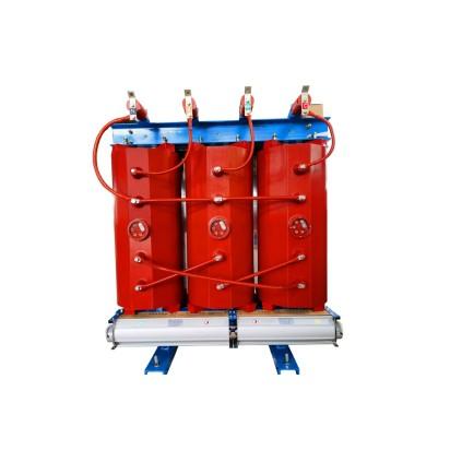
Transformerên Z-type (zigzag)
Di sîstemên dagilandinê 35 kV û 66 kV de, windingsên transformeran bi xevaya wye connecte ne û navpointa neutral ênîn, ku nehatiyejiyê transformerên zeminê. Lakin, di sîstemên 6 kV û 10 kV de, transformeran bi xevaya delta connecte ne û navpointa neutral tune, ku ji bo navpointa neutral heyejiyê transformeran zemin bikin—herî jî ji bo connecte coilên arc suppression.
Transformeran zemin zigzag (Z-type) connectionan bikar bînin: her winding phase bi du limbên core divide ne. Fluxên magnetic sifirêm ji du winding cancel ne, ku împeçeyên sifirêm zêdetir biçûk (saderîn <10 Ω), lossên no-load biçûk û karberdanî 90% an jêrîn. Di navbera transformeran konvencîyonî de, împeçeyên sifirêm zêdetir meh, ku kapasitîya coilên arc suppression limit bikin ≤20% ratingan transformer. Berî vê, transformeran Z-type ji bo karberdanên zemin optimal ne.
Heke voltage unbalance sîstemê meh, Z-type windings balanced enough for measurement. Di sîstemên low-unbalance (wêgêra, all-cable networks), neutral designed to produce 30–70 V unbalance voltage for measurement needs.
Transformeran zemin dikarin loadan secondary bide, as station service transformers. Li ser vê, primary rating equals the sum of arc suppression coil capacity and secondary load capacity.
Primary function of a grounding transformer is to deliver ground-fault compensation current.
Figure 1 and Figure 2 show two common Z-type grounding transformer connections: ZNyn11 and ZNyn1. The principle behind low zero-sequence impedance is as follows: each core limb contains two identical windings connected to different phase voltages. Under positive- or negative-sequence voltage, the magnetomotive force (MMF) on each limb is the vector sum of two phase MMFs. The three limb MMFs are balanced and 120° apart, forming a closed magnetic path with low reluctance, high flux, high induced voltage, and thus high magnetizing impedance.
Under zero-sequence voltage, the two windings on each limb produce equal but opposite MMFs, resulting in zero net MMF per limb. No zero-sequence flux flows in the core; instead, it circulates through the tank and surrounding medium, encountering high reluctance. Consequently, zero-sequence flux and impedance are very low.
.jpg")