What are the possible causes of cracking failure in CT terminal blocks within GIS equipment?

07/07/2025

Gas - insulated switchgear (GIS) , often called “SF6 combined electrical apparatus”, is widely used in power systems for its high reliability, small footprint, low noise, and low loss. It encloses high - voltage devices like circuit breakers, fast grounding switches, current transformers, and busbars in a grounded metal shell filled with SF6 gas . Each device sits in a separate gas chamber with different pressures. The CT terminal block divides gas chambers, connects components, and eases maintenance . A converter station found a 750kV GIS CT gas chamber’s pressure dropped ~0.05MPa daily, persisting after gas refilling. Thus, we analyzed the CT terminal block’s failure.
1 Overview and Cracking Analysis of the Terminal Block
1.1 Overview
Put into operation on 2017 - 06 - 23, the terminal block leaked gas on 2021 - 11 - 06 and showed cracks on 2021 - 11 - 08. The flat side is CT - side, convex is non - CT - side, with 12 outer threaded holes. CT - side has three circles of equidistant yellow copper terminal posts (1, 8, 15 per circle from inside); non - CT - side’s outermost circle has 15 posts (A1 - A5, B1 - B5, C1 - C5 counterclockwise), matching CT - side in middle circles.
1.2 Macroscopic Inspection
A ~30cm - long crack was found on the convex side, at the raised edge’s turn, split into two sections: a wide - opened long crack (A1 - B1) and a small - opened short crack (C5 - A1, barely visible). Penetrant testing followed to check for more cracks.

1.3 Penetrant Testing

Penetrant testing was conducted on both sides of the terminal block:

  • Convex side: Two cracks were found, consistent with macroscopic inspection in morphology and length (240mm and 60mm). The short crack became obvious after testing, and no other cracks were detected.
  • Flat side: Two cracks of different lengths (approximately 20mm and 8mm) were found at the inner sealing ring. They did not penetrate through, with an end - to - end distance of about 20mm.
1.4 Fracture Surface Inspection
A section cut from A4 showed non - CT - side penetrative cracks and CT - side non - penetrative ones. Square conductive sheets and hexagonal nuts inside had structural abrupt changes,with penetrant back - seepage (gaps between metal inserts and epoxy resin). Fine cracks (30° to the terminal block axis) and uneven, spotted contact surfaces (with 45° - angled cracks) were seen.
1.5 Force Calculation
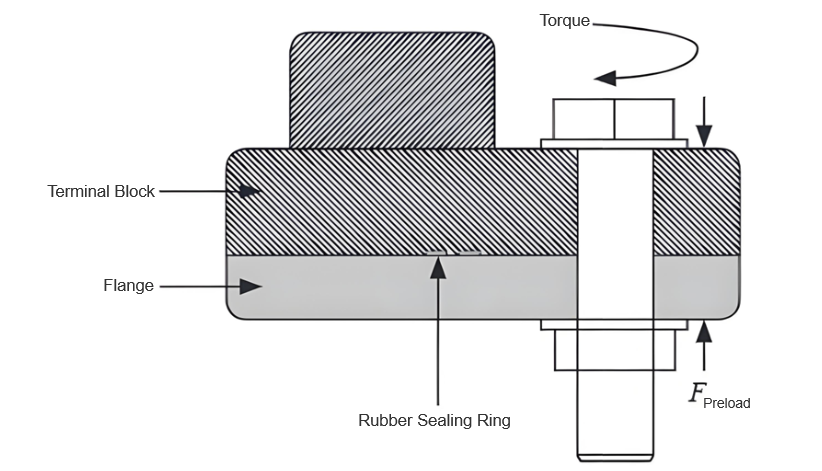
With the manufacturer’s 25Nm bolt torque, using T = kFd ((k = 0.15), the single - bolt vertical preload was 13.9kN. Simulating max preload (M12 bolt, 50cm torque wrench) gave 220Nm torque (44Nm via a 10cm - arm wrench), raising preload to 24.4kN (1.76× standard). The 30° - angled, 31.78mm - long fracture had a 10.78mm discontinuous joint (resin stress increase). Excessive preload and stress concentration caused crack initiation and propagation in resin.
2 Causes of Cracking
Excessive bending stress on the discontinuous seat structure (edge bolt hole - terminal post) caused penetrative cracks. Improper tools/over - tightening led to excessive bolt preload. CT - side gas pressure
added to bending stress. Poor metal - resin bonding (gaps) reduced bearing cross - section and caused stress concentration. Combined, these cracked the terminal block, leaking gas.
3 Preventive Measures
Use torque wrenches per manufacturer specs to avoid over - tightening. Follow gas - filling processes to prevent pressure differences. Optimize terminal block design/casting to avoid stress - causing gaps/sharp inserts. Strengthen quality checks to reject faulty products.
4 Conclusion
CT terminal block cracking in SF6 apparatus resulted from improper bolt - tightening (excessive preload). The proposed measures guide other power users.

Hey there! I'm an electrical engineer specializing in Failure and Maintenance. I've dedicated my career to ensuring the seamless operation of electrical systems. I excel at diagnosing complex electrical failures, from malfunctioning industrial motors to glitchy power distribution networks. Using state - of - the - art diagnostic tools and my in - depth knowledge, I pinpoint issues quickly. On this platform, I'm eager to share my insights, exchange ideas, and collaborate with fellow experts. Let's work together to enhance the reliability of electrical setups.

Transformer Detection, Testing, Maintenance and Servicing
Transformer testing, inspection, and maintenance are essential tasks to ensure normal operation and extend the service life of transformers. Below are some recommended steps:Visual Inspection: Regularly inspect the transformer's exterior, including the enclosure, cooling system, and oil tank. Ensure the enclosure is intact, free from corrosion, damage, or leakage.Insulation Resistance Testing: Use an insulation resistance tester to check the transformer's insulation system. Verify that the insul
Vziman
08/29/2025
What are the Common Operation Faults of Indoor Load Switches?
Common operational faults of indoor load switches primarily concentrate on three core aspects: mechanical operation, electrical performance, insulation, and arc extinguishing. These issues can be broadly categorized as follows and are often related to component aging, environmental influences, or improper operation.1.Mechanical Faults The most typical issue is abnormal operation during opening and closing. This includes excessive resistance, jamming, or even refusal to operate when manually turn
08/27/2025
What should be done if the fuse element on the high-voltage side of the transformer melts?
If the fuse element on the high-voltage side of the transformer blows or the circuit trips, the first step is to determine whether one phase, two phases, or all three phases are interrupted. This can be determined according to the fault symptoms as shown in the following table:When a fuse element blows, first check whether the high-voltage side fuse or the lightning arrester gap has short-circuited to ground. If no abnormalities are found during external inspection, it can be concluded that an i
08/26/2025
Usage and Maintenance of Fuses
Use and MaintenanceIn low-voltage power distribution systems, fuses are protective electrical devices. Widely used for power grid and electrical equipment protection, fuses automatically cut off circuits when short circuits or overloads occur in the grid or equipment, preventing damage to electrical devices and preventing accidents from spreading.A fuse consists of an insulating base (or support), contacts, and a fuse element. The fuse element is the primary working component, acting like a spec
08/26/2025
Inquiry
Download
IEE-Business is dedicated to serving the personnel in the global power industry.
Join IEE-Business, not only can you discover power equipment and power knowledge, but also canhnd like - minded friends!