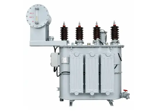
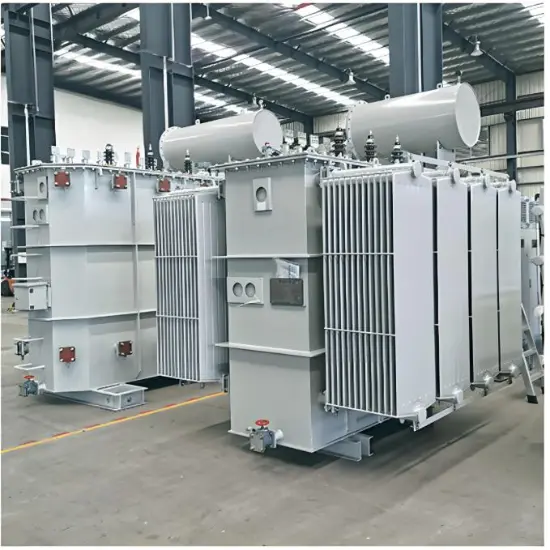
Abnormal dissolved gas analysis (DGA) results, gas relay operation, and excessive temperature rise in oil-immersed earthing transformers are usually not isolated issues. They are often combined indications of internal overheating, partial discharge, arcing, or insulation deterioration. A reliable diagnosis should integrate dissolved gas analysis, thermal condition monitoring, and electrical tests, with reference to applicable IEC standards.
Neutral Grounding Transformer Manufacturer
1. DGA Abnormalities: Chemical Indicators of Internal Faults
Dissolved gas analysis is one of the most effective methods for detecting latent faults in oil-immersed transformers. According to IEC 60599, key gases such as hydrogen (H₂), methane (CH₄), ethane (C₂H₆), ethylene (C₂H₄), acetylene (C₂H₂), carbon monoxide (CO), and carbon dioxide (CO₂) can help identify the type of internal fault.
| Characteristic Gas |
Possible Fault Type |
Typical Causes |
| Mainly H₂ |
Partial discharge |
Moisture in insulation, gas bubbles, high electric stress |
| Mainly CH₄ and C₂H₄ |
Low-temperature overheating |
Local core overheating, loose connections |
| Mainly C₂H₄ |
Medium to high-temperature overheating |
Core multi-point grounding, stray flux heating |
| Presence of C₂H₂ |
High-temperature overheating or discharge |
Turn-to-turn short circuit, lead discharge, arcing |
| Elevated CO and CO₂ |
Solid insulation ageing |
Paper insulation carbonization or thermal degradation |
Key interpretation points:
- A single DGA result should not be used as the only basis for fault diagnosis. Gas generation rate and gas ratios, such as the IEC ratio method or Duval Triangle method, should be considered.
- Even if gas concentrations are below the typical concern levels, a rapid increase in gas generation rate should be treated as abnormal.
- If the earthing transformer is equipped with an on-load or off-circuit tap changer, the DGA results from the tap changer oil compartment should be analyzed separately. Duval Triangle 2 may be referenced where applicable.
- The appearance of acetylene requires special attention, as it may indicate high-energy discharge or a serious fault. However, the final assessment should be based on gas concentration, gas generation rate, and electrical test results.
2. Gas Relay Operation: A Direct Indicator of Fault Severity
Gas relays are normally classified as light gas protection, which issues an alarm signal, and heavy gas protection, which initiates a trip. After gas relay operation, free gas from the relay and oil samples from the main tank should be collected and analyzed in accordance with IEC 60599.
Common causes of light gas operation:
- Minor internal overheating or partial discharge producing small amounts of combustible gas;
- Air ingress due to incomplete air release after oil filtration or oil top-up, or due to poor sealing;
- Low oil level causing gas accumulation in the relay;
- Oil flow disturbance caused by external short-circuit impact.
Common causes of heavy gas operation:
- Turn-to-turn, layer-to-layer, or phase-to-phase winding short circuits;
- Internal arcing;
- Severe core overheating accompanied by strong oil flow impact;
- Severe through-fault short circuits near the transformer.
Note: If the light gas relay operates and the collected gas is non-combustible, sealing, oil level, and air release should be checked first. If the gas is combustible, or if the heavy gas relay operates, the transformer should not be re-energized until the cause has been identified.
3. Excessive Temperature Rise: Visible Signs of Thermal Abnormalities
Temperature rise assessment should be carried out in accordance with IEC 60076-2:2011, which distinguishes three main temperature rise categories:
- Top oil temperature rise: the difference between top oil temperature and cooling medium temperature under rated continuous load;
- Average winding temperature rise: usually determined by the resistance method;
- Winding hot-spot temperature rise: reflects the thermal stress at the hottest point of the winding insulation.
According to IEC 60076-2:2011, typical temperature rise limits for oil-immersed transformers under rated continuous load are: top oil temperature rise not exceeding 60 K, and average winding temperature rise not exceeding 65 K. The hot-spot temperature rise depends on the insulation thermal class, cooling method, and thermal model. For Class A insulation, the reference hot-spot temperature for normal ageing is commonly taken as 98 °C. The actual applicable limits should be confirmed based on the equipment nameplate, manufacturer’s technical documents, and the applicable version of IEC 60076-2.
Overload evaluation may refer to IEC 60076-7, which classifies overloads into normal cyclic loading, long-time emergency loading, and short-time emergency loading. Permissible overload levels depend on the initial load ratio, ambient temperature, and cooling method.
External causes:
- Overload operation;
- Cooling system failure, such as blocked radiators or stopped fans and oil pumps;
- High ambient temperature or poor ventilation;
- Abnormal temperature measuring devices, which may give false high readings.
Internal causes:
- Core multi-point grounding causing circulating current;
- Turn-to-turn, layer-to-layer, or strand-to-strand winding short circuits;
- Poor contact in tap changers;
- Local overheating of clamping structures or tank walls caused by stray flux;
- Deterioration of insulating oil, reducing heat dissipation and insulation performance.
4. Special Considerations for Earthing Transformers
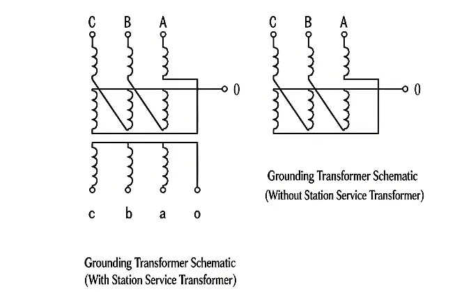
Earthing transformers are commonly designed with a zigzag connection or a dedicated earthing winding. Under normal operating conditions, their load is relatively low. However, during a single-phase earth fault, they may be required to carry a relatively high zero-sequence current for a short period. The following points should be given special attention during fault diagnosis:
- Duration of zero-sequence current and its thermal accumulation effect;
- Influence of the neutral earthing method on fault current magnitude;
- Core grounding current condition. The acceptable core grounding current should be verified against the manufacturer’s technical documents or project specifications. If the value increases significantly, the possibility of multi-point core grounding should be evaluated together with DGA results, insulation tests, and site operating conditions.
5. Integrated Diagnosis and Handling Procedure
| Observed Condition |
Possible Fault Direction |
Recommended Actions |
| Increased total hydrocarbons, mainly C₂H₄/CH₄, no C₂H₂ |
Overheating fault |
Check core grounding current, tap changer, and cooling system |
| Increased H₂ with partial discharge signals |
Partial discharge or moisture |
Test moisture content, dielectric loss, and partial discharge |
| Appearance or rapid increase of C₂H₂ |
Discharge or short circuit |
Measure winding DC resistance and perform insulation tests |
| Light gas operation with non-combustible gas |
Air ingress or low oil level |
Check sealing, perform air release, and top up oil if necessary |
| Increased temperature rise with abnormal DGA |
Internal overheating or discharge |
Evaluate load, cooling condition, and electrical test results |
General handling principles:
- Verify the reliability of field data, including temperature indicators, load current, oil level, and cooling system status;
- Collect gas and oil samples for DGA and check gas combustibility;
- Exclude external factors such as cooling system faults, sealing problems, overload, and temperature measurement errors;
- Carry out electrical tests, such as winding DC resistance, insulation resistance, dielectric loss, and core grounding current measurement;
- Decide whether to shorten the monitoring interval, arrange outage maintenance, or take emergency shutdown measures according to the fault nature.
Reference Standards
- IEC 60599 — Guide for the interpretation of dissolved and free gases in mineral-oil-filled electrical equipment
- IEC 60076-2:2011 — Temperature rise for liquid-immersed transformers
- IEC 60076-7 — Loading guide for mineral-oil-immersed power transformers
This article is for technical reference only. Actual diagnosis and operational decisions should be based on the equipment nameplate, manufacturer’s technical documents, site test results, and the applicable versions of IEC or national standards.
Dissolved gas analysis results should be evaluated together with gas generation rate, gas ratios, free gas analysis, load history, electrical tests, and site operating conditions. A single DGA result should not be used as the sole basis for fault determination.

 Login