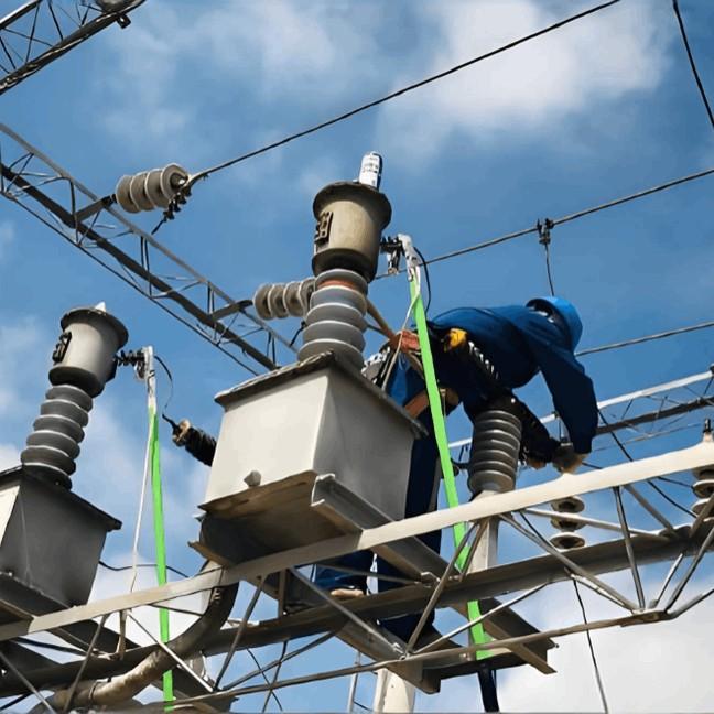
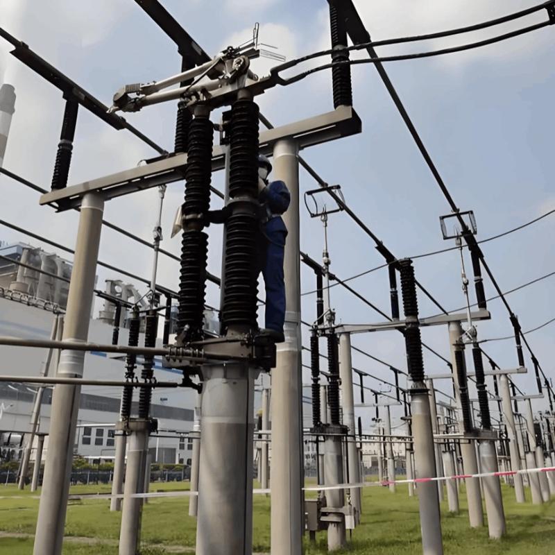
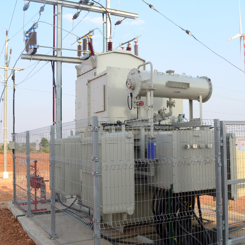
1. Methods for Detecting Busbar Discharge
1.1 Insulation Resistance Test
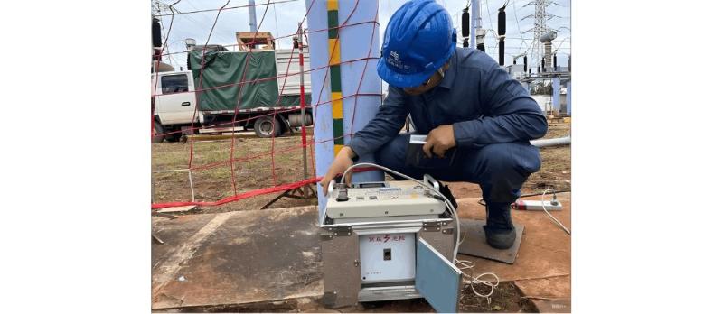
The insulation resistance test is a simple and commonly used method in electrical insulation testing. It is highly sensitive to through-type insulation defects, overall moisture absorption, and surface contamination—conditions that typically result in significantly reduced resistance values. However, it is less effective in detecting localized aging or partial discharge faults.
Depending on the equipment’s insulation class and testing requirements, common insulation resistance testers use output voltages of 500 V, 1,000 V, 2,500 V, or 5,000 V.
1.2 Power Frequency AC Withstand Voltage Test
The AC withstand voltage test applies a high-voltage AC signal—higher than the equipment’s rated voltage—to the insulation for a specified duration (typically 1 minute unless otherwise stated). This test effectively identifies local insulation defects and evaluates the insulation’s ability to withstand overvoltages under real operating conditions. It is the most realistic and decisive insulation test for preventing insulation failures.
However, it is a destructive test that may accelerate existing insulation defects and cause cumulative degradation. Therefore, test voltage levels must be carefully selected in accordance with GB 50150–2006 Code for Acceptance Test of Electric Equipment in Electrical Installation Projects. Test standards for porcelain and solid organic insulation are shown in Table 1.
Table 1: AC Withstand Voltage Standards for Porcelain and Solid Organic Insulation
Various AC withstand voltage methods exist, including power frequency testing, series resonance, parallel resonance, and series-parallel resonance. For busbar discharge testing, standard power frequency AC withstand voltage testing is sufficient. The test setup should be determined based on the test voltage, capacity, and available equipment, typically using a complete AC high-voltage test set.
1.3 Infrared Testing
All objects with a temperature above absolute zero continuously emit infrared radiation. The amount of infrared energy and its wavelength distribution are closely related to the object’s surface temperature. By measuring this radiation, infrared thermography can accurately determine surface temperature—forming the scientific basis of infrared temperature measurement.
From the perspective of infrared monitoring and diagnostics, high-voltage equipment faults can be broadly classified into two categories: external and internal. External faults occur on exposed parts and can be directly detected using infrared instruments. Internal faults, however, are hidden within solid insulation, oil, or enclosures and are difficult to detect directly due to blocking by insulating materials.
Infrared diagnosis of busbar discharge involves temperature measurement, calculation of relative temperature difference (accounting for ambient temperature), and comparison with normally operating busbars. This allows for intuitive identification of overheating and discharge locations.
2. Application of New Technologies
2.1 Ultraviolet (UV) Imaging Technology
When the local electric stress on energized equipment exceeds a critical threshold, air ionization occurs, leading to corona discharge. High-voltage equipment often experiences discharges due to poor design, manufacturing, installation, or maintenance. Depending on the electric field strength, this may result in corona, flashover, or arcing. During discharge, electrons in the air gain and release energy—emitting ultraviolet (UV) light when energy is released.
UV imaging technology detects this UV radiation, processes the signal, and overlays it onto a visible-light image displayed on a screen. This enables precise location and intensity assessment of corona, providing reliable data for evaluating equipment condition.
2.2 Ultrasonic Testing (UT)
Ultrasonic testing (UT) is a portable, non-destructive industrial inspection method. It enables fast, accurate, and non-invasive detection, localization, evaluation, and diagnosis of internal defects such as cracks, voids, porosity, and impurities—both in laboratories and field environments.
Ultrasonic waves are elastic waves that propagate through gases, liquids, and solids. They are categorized by frequency: infrasound (<20 Hz), audible sound (20–20,000 Hz), ultrasound (>20,000 Hz), and hypersonic waves. Ultrasound behaves similarly to light in terms of reflection and refraction.
As ultrasonic waves travel through a material, changes in acoustic properties and internal structure affect wave propagation. By analyzing these changes, ultrasonic testing assesses material properties and structural integrity. Common methods include through-transmission, pulse-echo, and tandem techniques.
Digital ultrasonic flaw detectors emit ultrasonic waves into the test object and analyze reflections, Doppler effects, or transmission to obtain internal information, which is then processed into images. This technology is highly effective for assessing the insulation condition of operating high-voltage busbars.
3. Specific Solutions for High-Voltage Busbar Discharge
If abnormal discharge in high-voltage busbars is not addressed promptly, it can lead to insulation overheating, eventual insulation failure, and even major blackouts. Therefore, discharge faults must be resolved quickly and prevented proactively.
3.1 Strict Commissioning and Acceptance Testing
Many busbar discharge faults stem from poor workmanship or lack of responsibility during construction. Test personnel must strictly follow codes and standards during acceptance testing of new equipment, identifying potential discharge risks early and correcting them before commissioning.
3.2 Replace Aging Busbar Insulators
Most operational busbar discharges are caused by aging of support insulators. A detailed inventory should be maintained, and insulators should be replaced based on service life to ensure adequate insulation strength.
3.3 Comprehensive Analysis Using Insulation and Diagnostic Tests
Insulation tests can effectively detect severe discharge faults. However, for early-stage or hidden discharges, advanced diagnostic methods such as infrared imaging, UV imaging, and ultrasonic testing are required for early detection and intervention. Therefore, a comprehensive analysis combining both insulation tests and diagnostic tests is essential to effectively prevent and mitigate busbar discharge failures.


