
A sensor is an electrical device that detects and responds to a certain sort of signal, such as optical or electrical. The use of sensor methods in voltage (or) current measurement has become an excellent alternative for voltage and current measurement methods. Sensors provide many benefits over traditional techniques of measurement, including reduced size & weight, high safety, high precision, non-saturability, eco-friendliness, and so on. It is possible to combine current and voltage monitoring into a single physical device with small and solid dimensions. This post gives a brief description of the voltage sensor & how it works.

This sensor measures, calculates, and determines the voltage supply. This sensor can detect the amount of AC or DC voltage. This sensor’s input may be voltage, and its output can be
Switches,
Analogue voltage signals,
Current signals,
Audio signals, and so on.
Some sensors produce sine waveforms or pulse waveforms, while others may produce
AM (Amplitude Modulation),
PWM (Pulse Width Modulation), or
FM waveforms (Frequency Modulation).
The voltage divider may affect the measurement of these sensors.
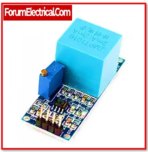
This sensor has both input and output. The input side consists mostly of two pins, positive and negative. The device’s two pins may be linked to the sensor’s positive and negative pins. The device’s positive and negative pins may be linked to the sensor’s positive and negative pins. This sensor’s output primarily contains
Supply voltage (Vcc),
Ground (GND), and
Analogue o/p data.
Voltage sensors are capable of detecting a wide range of phenomena, including the following:
1). Magnetic Fields
2). Electromagnetic Fields
3). Contact Voltage
Sensors that are primarily designed to monitor contact voltage have a broad range of potential applications and sectors in which they might be used. Battery monitoring is a typical example of an application. One piece of equipment may have a battery placed in it, but some months later, the battery may get dislodged and fall out of its proper location. This sensor will be able to identify that there has been a decrease in the contact voltage and will notify the CMMS of the change. The next step is for a maintenance professional to follow up and re-establish contact with the user.
These sensors are divided into two types:
Resistive voltage sensors and
Capacitive voltage sensors.
This sensor primarily consists of two circuits:
a voltage divider and
a bridge circuit.
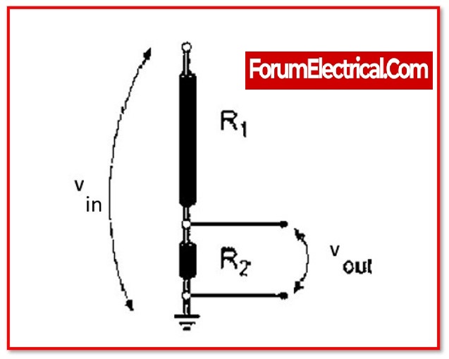
In the circuit, the resistor serves as a sensing element. To create a voltage divider circuit, split the voltage into two resistors, such as
a reference voltage and
a variable resistor.
This circuit is powered by a voltage source. The resistance in the circuit determines the output voltage. As a result, the voltage change might be increased.

Four resistors may be used to construct the bridge circuit. Any of these resistors may be tested using the voltage detector.
The voltage difference may be seen immediately. This difference alone may be amplified however the difference inside the voltage divider circuit not simply amplified.
Vout = (R1/R


