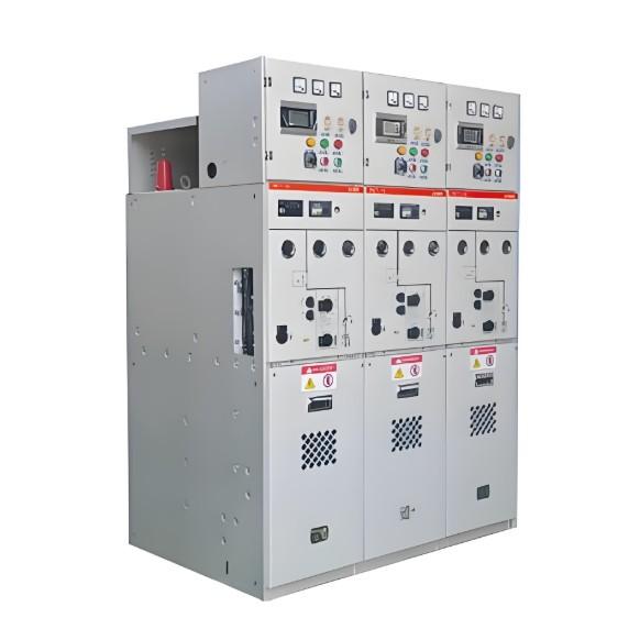
What is Low Voltage Switchgear?
Low Voltage Switchgear Definition
Low voltage switchgear is defined as electrical switchgear rated up to 1kV, including protective devices like circuit breakers and fuses.
Components of LV Switchgear
LV switchgear includes devices such as circuit breakers, isolators, and earth leakage circuit breakers to protect the system.
Incomer Function
The incomer feeds incoming electrical power to the incomer bus. The switchgear used in the incomer should have a main switching device. The switchgear devices attached with incomer should be capable of withstanding abnormal current for a short specific duration in order to allow downstream devices to operate. But it should be cable of interrupting maximum value of the fault current generated in the system. It must have an interlocking arrangement with downstream devices. Generally air circuit breakers are preferably used as interrupting device. Low voltage air circuit breaker is preferable for this purpose because of the following features.

Simplicity
Efficient performance
High normal current rating up to 600 A
High fault withstanding capacity upto 63 kA
Although air circuit breakers have long tripping time, big size, high cost but still they are most suitable for low voltage switchgear for the above-mentioned features.
Sub-Incomer Role
Next downstream part of the LV Distribution board is sub – incomer. These sub-incomers draw power from main incomer bus and feed this power to feeder bus. The devices installed as parts of a sub – incomer should have the following features.
Ability to achieve economy without sacrificing protection and safety.Need for relatively less number of interlocking since it cover limited are of network.ACBs (Air Circuit Breakers) and switch fuse units are generally used as sub – incomers along with molted case circuit breakers (MCCB).
Feeder Types and Protection
Feeders connect to the feeder bus to supply different loads such as motors, lighting, industrial machinery, air conditioners, and transformer cooling systems. All feeders are mainly protected by switch fuse units. Depending on the load type, different switchgear devices are selected for each feeder.
Motor Feeder
Motor feeder should be protected against over load, short circuit, over current up to locked rotor condition and single phasing.
Industrial Machinery Load Feeder
Feeder connected industrial machinery load like oven, electroplating bath etc are commonly protected by MCCBl and switch fuse disconnector units.
Lighting Load Feeder
This is protected similar to industrial machinery load but additional earth leakage current protection is provided in this case to reduce any damage to life and property that could be caused by harmful leakages of current and fire.
In an LV switchgear system, appliances are protected against short circuits and overloads by electrical fuses or circuit breakers. However, operators are not fully protected from appliance faults. An earth leakage circuit breaker (ELCB) solves this issue. ELCBs detect leakage currents as low as 100 mA and disconnect the appliance in under 100 milliseconds.
A typical diagram of low voltage switchgear is shown above. Here the main incomer comes from LV side of an electrical transformer. This incomer through an electrical isolator as well as an MCCB (not shown in the figure) feeds the incomer bus. Two sub-incomers are connected to the incomer bus and these sub-incomers are protected by means of either switch fuse unit or air circuit breaker.
These switches are so interlocked along with bus section switch or bus coupler that only one incomer switch can be put on if bus section switch is in on position and both sub incomer switches can be put on only if bus section switch is at off position. This arrangement is fruitful for preventing any mismatch of phase sequence between the sub – incomers. The different load feeders are connected to any of both sections of the feeder bus.
Here motor feeder is protected by thermal overload device along with conventional switch fuse unit. Heater feeder is protected only by conventional switch fuse unit. The domestic lighting and AC loads are separately protected by a miniature circuit breaker along with common conventional switch fuse unit. This is most basic and simple scheme for low voltage switchgear or LV distribution board.