What aspects should be paid attention to when installing medium-voltage switch cabinets during the initial stage of subway operation?

06/11/2025

1. Statistics on Common Faults of Medium-Voltage Switchgear in the Early Operation Stage
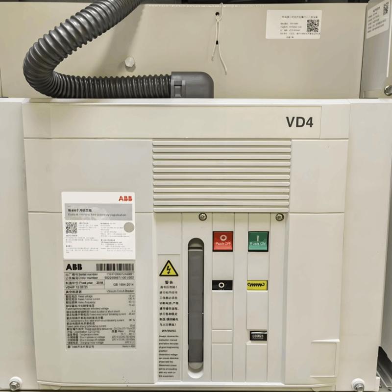
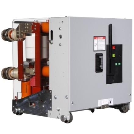
As project participants, we found during the early operation of a new metro line: 21 sets of power supply equipment were put into use, with a total of 266 accident phenomena in the first year. Among them, 77 faults occurred in medium-voltage switchgear, accounting for 28.9%—significantly higher than faults in other equipment. Statistical analysis shows that major fault types include: protection device signal anomalies, air chamber pressure sensor false alarms, live indication failures on the feeder cable side of switches, and loose voltage busbars between cabinets. These issues directly affect the operational safety and quality of medium-voltage switchgear.
2. Fault Causes and Rectification Measures
We conducted a 3-month tracking statistics on fault data, comprehensively investigated causes, and formulated rectification plans. After six months of rectification, the fault frequency significantly decreased, and operational stability improved. The specific analysis is as follows:
2.1 Signal Faults
  • Cause: Internal board failures of live line indicators were the main reason for frequent signal false alarms in the early stage.
  • Rectification: After inspecting equipment across the line, all damaged live line indicators were replaced to ensure accurate signal transmission.

2.2 Switch Air Chamber Pressure Faults

  • Cause: Loose plug-in connectors of air chamber pressure sensors in 35kV switchgear led to poor contact and signal mistransmission.
  • Rectification: All air chamber pressure sensor plugs were replaced, and circuit connections were reinforced to eliminate contact hidden dangers.

2.3 Communication Faults

  • Cause: Hardware board defects or software operation anomalies in protection devices triggered abnormal monitoring conditions.
  • Rectification: Faulty hardware boards were replaced, and software was upgraded to optimize communication stability.

2.4 Voltage Phase Loss Faults

  • Cause: The voltage busbar in the cabinet top circuit loosened due to external forces, preventing the protection module from normal signal acquisition.
  • Rectification: A bridge was installed at the top of the cabinet to fix the voltage busbar, standardize wiring processes, and eliminate phase loss faults caused by loose terminals.
3. Follow-up Maintenance Planning
From equipment operation and maintenance experience, the early operation stage is a high-risk period for faults, where design defects, installation craftsmanship, and operational environment issues tend to emerge intensively. Incomplete initial defect inspection directly threatens traffic safety. From a cost perspective, defect handling during the warranty period can obtain free technical support from manufacturers, while maintenance costs will increase significantly after the warranty expires. Therefore, we have formulated the following strategies:
  • Maintenance Process Optimization: Include voltage busbar terminal inspections in the annual maintenance plan, and simultaneously verify switch position status.
  • Reliability Enhancement: Adopt scientific maintenance strategies to extend equipment service life and reduce life-cycle costs through regular inspections and condition monitoring.

4. Conclusion
Incorporating medium-voltage switchgear in the early operation stage into key maintenance scopes helps accurately statistical analyze equipment faults. We must use fault data as a basis to formulate maintenance outlines, dynamically adjust maintenance plans, and improve equipment reliability through standardized operations to ensure metro safety.

As an expert in the application and trends of electrical equipment, I have a profound mastery of knowledge in circuits, power electronics, etc. I possess a comprehensive set of abilities including equipment design, fault diagnosis, and project management. I can precisely grasp the industry's pulse and lead the development of the electrical field.

Application of Indoor Load Switches in Indoor Power Distribution Rooms
In indoor switchgear rooms, indoor load switches are key devices designed to meet the core requirements of "medium and low-voltage distribution, flexible control, and simplified protection." Their application centers on three primary scenarios: "circuit control, safety isolation, and fault coordination." The specific implementation methods and value are as follows:1.Power Control Unit for Terminal Loads: Load switches are commonly used in branch circuits of low-voltage distribution panels within
08/28/2025
Differences Between Load Switches and Disconnectors
What is a Load Switch?A load switch is a control device equipped with a simple arc-extinguishing mechanism, capable of opening and closing circuits under load. It can interrupt a certain level of load current and overload current, but cannot interrupt short-circuit current. Therefore, it must be used in series with a high-voltage fuse, which relies on the fuse to clear short-circuit currents.Functions of a Load Switch:Switching and Closing Function: Due to its certain arc-extinguishing capabilit
08/27/2025
Combined Application of Fuses
Medium-voltage current-limiting fuses are primarily used for protecting loads such as transformers and motors. A fuse is a device that, when the current exceeds a given value for a sufficiently long duration, interrupts the circuit in which it is inserted by melting one or more specially designed and proportioned components. Current-limiting fuses may have difficulty clearing intermediate current values (overloads between 6 to 10 times the rated current), so they are typically used in combinatio
08/27/2025
Operation and Use of Expulsion Type Isolators and Expulsion Type Fuses
High-voltage disconnect switches (or fuses) do not have arc-extinguishing capability, but they provide a clearly visible break point. Therefore, they are used solely as isolation components in a circuit. They are installed at the beginning of a circuit or in front of components requiring maintenance. When a circuit needs to be de-energized for maintenance, the power is first interrupted using a switching device, and then the disconnect switch is opened. This ensures a clearly visible break in th
08/26/2025
Inquiry
Download
IEE-Business is dedicated to serving the personnel in the global power industry.
Join IEE-Business, not only can you discover power equipment and power knowledge, but also canhnd like - minded friends!