What is Diffusion Capacitance?

Encyclopedia
09/20/2024

Diffusion capacitance definition


Diffused capacitance is a kind of differential capacitance effect of p-n junction when it is positively biased. It is caused by the diffusion process of different types of materials in semiconductor devices such as PN junction or MOSFET, that is, a few carriers in the doped region diffuse to the undoped region to form a space charge region, and finally appear as a capacitance effect.


Basic principle


When the PN junction is forward-biased, carriers (electrons and holes) will diffuse from the P and N regions to each other, respectively. In the process of diffusion, P area has accumulated a certain amount of non-equilibrium Jane (electronic), N area accumulated a certain amount of non-equilibrium Jane (hole). These accumulated non-equilibrium minority particles form a certain charge store, like a capacitor, with the ability to store chargThe size of diffusion capacitance is related to the forward bias voltage, temperature and the properties of semiconductor materials. The larger the forward bias voltage, the larger the diffusion capacitance.


The formation of the diffusion capacitance


When an AC voltage is applied to a semiconductor junction, the concentration of the minority varies with the voltage. These minority particles move randomly in the semiconductor and accumulate near the semiconductor junction. This accumulation is equivalent to a capacitance effect, namely the diffusion capacitance.


The expression for diffusion capacitance can usually be written as:


4dae19fa503024e02f0565d6f5a337e0.jpeg


  • CD is the diffusion capacitance.

  • Qn is the minority charge.

  • V is the applied voltage.


Diffusion capacitance in a diode


In diodes, diffused capacitors mainly appear in the forward bias state. When the diode is forward-biased, minority particles (such as holes in N-type semiconductors) are injected into the P-region, resulting in a change in minority concentration. The change of concentration of Jane formed a capacitance effect, namely the diffusion capacitance.


Diffusion capacitance in a transistor


In transistors (such as BJT, MOSFETs, etc.), the diffusion capacitance also exists between the base and the emitter. When the transistor work in high frequency or high speed condition, the influence of the diffusion capacitance more apparent, because it affects the gain of the transistor and frequency response.


Effect of diffusion capacitance


The influence of diffusion capacitance in semiconductor devices is mainly reflected in the following aspects:


  • High frequency performance: In high frequency applications, diffusion capacitors limit the bandwidth of the device and affect its high frequency performance.


  • Switching speed: in switching applications, the diffusion capacitance can affect the speed of switching devices, increase switching loss.


  • Signal distortion: In amplifiers, diffused capacitors may introduce additional phase delay, resulting in signal distortion.


Calculation formula


The calculation of diffusion capacitance is usually based on models in semiconductor physics. For a diode, the diffusion capacitance can be approximated as:


29baf730ba45a4b4a6ed1b5622bbcf9e.jpeg


  • Q is the electronic charge.


  • NA is doping concentration


  • μn is electron mobility.


  • ϵr is the relative dielectric constant.


  • ϵ0 is the dielectric constant of vacuum.


  • VT is thermal voltage, n = kT/q, k is the boltzmann constant, T is the absolute temperature.


  • Vbi is the built-in potential.


Apply


  • High frequency circuits: In radio frequency (RF) and microwave circuits, the effect of diffusion capacitance cannot be ignored.


  • High-speed digital circuit: in high-speed digital circuit, the diffusion capacitance can affect the signal rise time and fall time.


  • Power management: In a power management circuit, diffusion capacitance affects the efficiency of the switching power supply.


Encyclopedia

The Electricity Encyclopedia is dedicated to accelerating the dissemination and application of electricity knowledge and adding impetus to the development and innovation of the electricity industry.

What is Biot Savart Law?
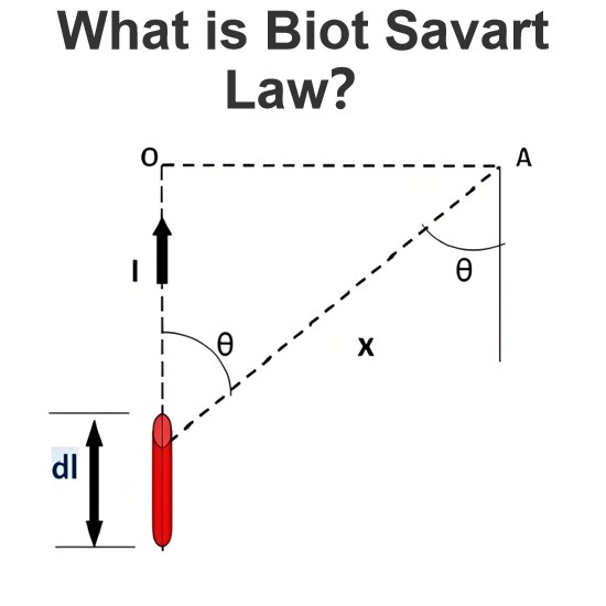
The Biot-Savart Law is employed to determine the magnetic field intensity dHnear a current-carrying conductor. In other words, it describes the relationship between the magnetic field intensity generated by a source current element. This law was formulated in 1820 by Jean-Baptiste Biot and Félix Savart. For a straight wire, the direction of the magnetic field adheres to the right-hand rule. The Biot-Savart Law is also referred to as Laplace’s law or Ampère’s law.Conside
Edwiin
05/20/2025
What is Peak Inverse Voltage (PIV)?
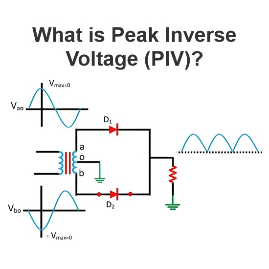
DefinitionThe maximum value of the reverse voltage that a PN junction or diode can withstand without damage is termed thePeak Inverse Voltage (PIV). This PIV rating is specified and explained in the datasheet provided by the manufacturer.However, if the voltage across the junction under reverse bias exceeds this specified value, the junction will be damaged.As shown in the figure above, a PN junction or diode is commonly used as a rectifier, i.e., to convert alternating current (AC) to direct cu
Edwiin
05/19/2025
What is Magnetoresistor?
Definition: When the resistance of certain metals and semiconductor materials changes in the presence of a magnetic field, this phenomenon is referred to as the magnetoresistance effect. The components that exhibit this effect are called magnetoresistors. Put simply, a magnetoresistor is a type of resistor whose resistance value fluctuates with the strength and direction of an external magnetic field.Magnetoresistors play a crucial role in detecting the presence of a magnetic field, measuring it
Encyclopedia
05/10/2025
How does the input voltage affect the current flowing through the load resistor in an ideal transformer?
How Input Voltage Affects the Current Through a Load Resistor in an Ideal TransformerAn ideal transformer is one that assumes no energy losses (such as copper loss or iron loss). Its primary function is to change the levels of voltage and current while ensuring that the input power equals the output power. The operation of an ideal transformer is based on the principle of electromagnetic induction, and there is a fixed turns ratio n between the primary and secondary coils, given by n=N2 /N1, whe
Encyclopedia
01/24/2025
Inquiry
Download
IEE-Business is dedicated to serving the personnel in the global power industry.
Join IEE-Business, not only can you discover power equipment and power knowledge, but also canhnd like - minded friends!