Preventing an interruption of service
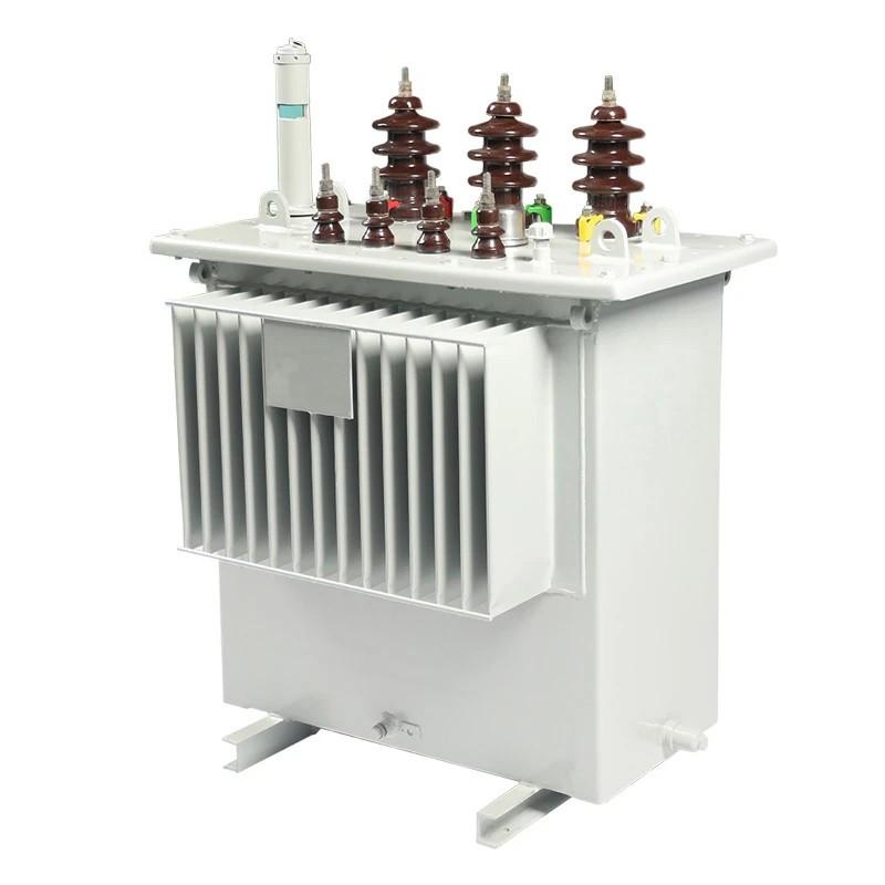
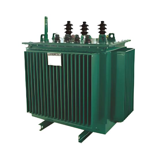
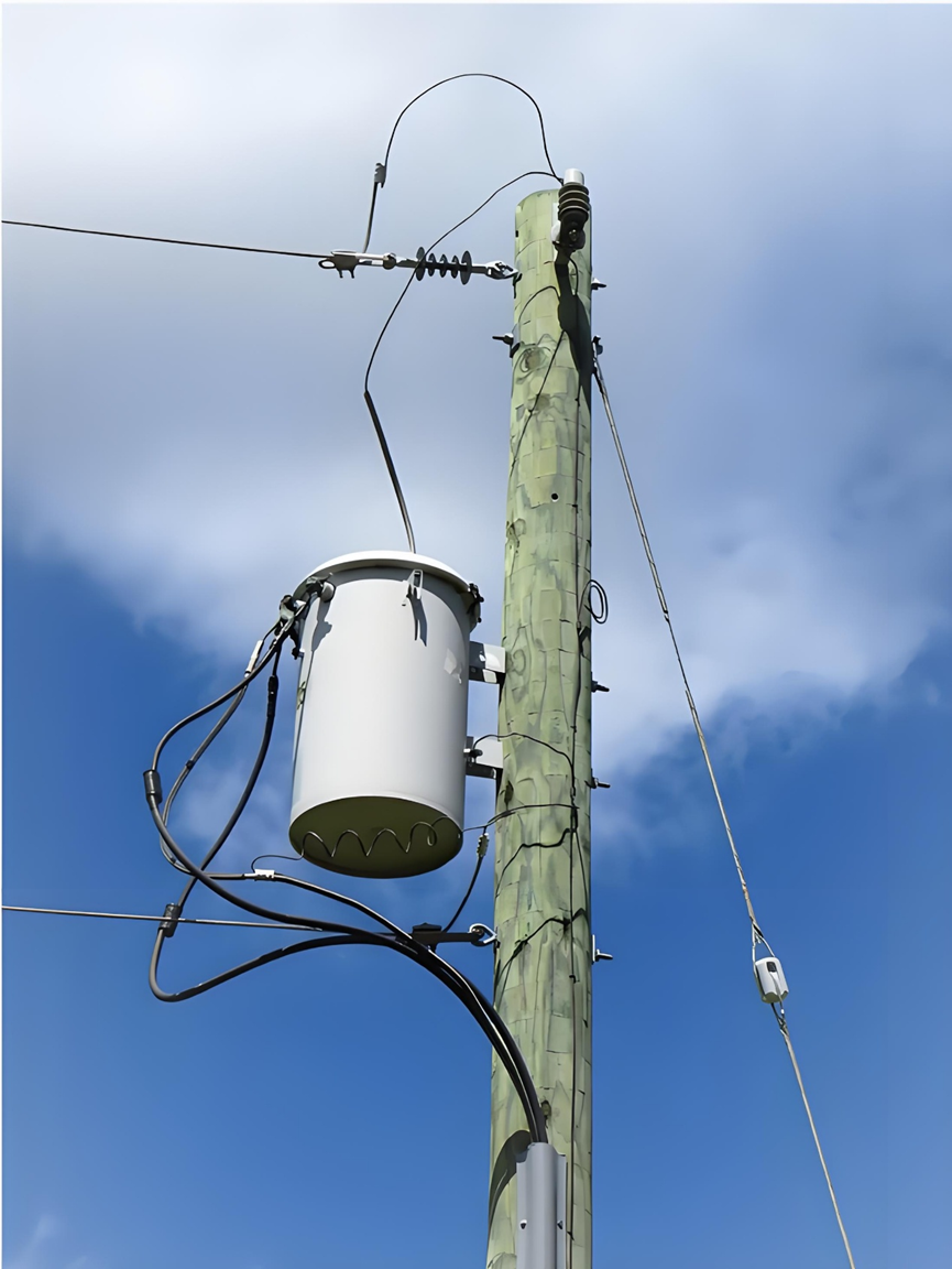
As is known, distribution transformers reduce the distribution or primary feeder voltage to the utilization voltage. They are linked to the primary feeder, sub - feeders, and laterals via primary fuses or fused cutouts. When a transformer fault or a low - impedance secondary - circuit fault takes place, the primary fuse disconnects the associated distribution transformer from the primary feeder. Reclosers are not addressed in this article.
The blowing of the primary fuse prevents an interruption of service to other loads supplied over the feeder, but interrupts service to all consumers supplied through its transformer.
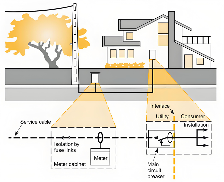
Fused cutouts (as shown in Figure 1, which are normally closed) provide a convenient means for disconnecting small distribution transformers for inspection and maintenance.
Due to the difference in the shape of the current - time curve of the primary fuse and the safe current - time curve of the distribution transformer, satisfactory overload protection for the distribution transformer cannot be achieved with a primary fuse. The shapes of these two curves are such that if a small - sized enough fuse is used to provide complete overload protection for the transformer, a great deal of the valuable overload capacity of the transformer will be lost, because the fuse will blow and prevent the transformer from making use of its overload capacity. Moreover, such a small - sized fuse often blows unnecessarily due to surge currents.
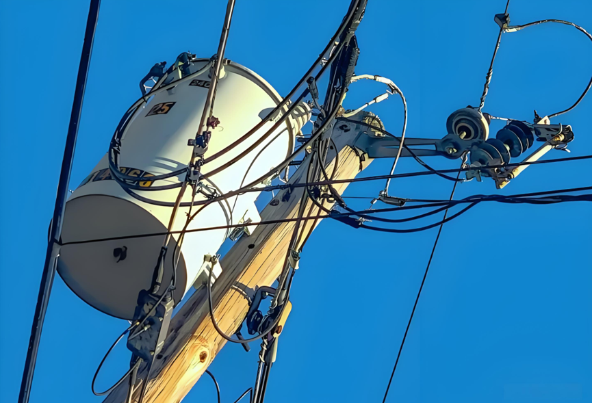
Distribution transformers connected to overhead open - wire feeders are often subject to severe lightning disturbances. To minimize insulation breakdown and transformer failures caused by lightning, lightning arresters are generally installed for these transformers.
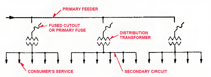
The secondary leads of a distribution transformer are typically solidly connected to radial secondary circuits. As depicted in Figure 1, consumer services are tapped from these circuits. This connection arrangement implies that the transformer lacks protection against overloads and high - impedance faults in its secondary circuits. In fact, relatively few distribution transformers are damaged by overloads.
This situation mainly stems from the application of distribution transformers, where their overload capacity is seldom fully utilized.
Regarding protection, fuses in the secondary leads of distribution transformers are scarcely more effective than primary fuses in preventing transformer burnouts, and for similar reasons. The appropriate approach to effectively safeguard a distribution transformer against overloads and high - impedance faults is to install a circuit breaker in the transformer's secondary leads. Crucially, the tripping curve of this circuit breaker must be precisely coordinated with the transformer's safe current - time curve.
Faults in a consumer's service connection, which runs from the secondary circuit to the service switch, are extremely rare. Therefore, installing a secondary fuse at the point where the service connection taps into the secondary circuit is not economically viable, except in special circumstances like large - scale services from underground secondary circuits.
As previously mentioned, the allowable voltage drop, measured from the point where the first distribution transformer connects to the primary feeder to the service switch of the last consumer on the feeder, should be economically allocated among the primary feeder, the distribution transformer, the secondary circuit, and the consumer's service connection.
Although these figures are typical for overhead systems that supply residential loads, significant differences can be expected in underground systems. Underground systems often utilize cable circuits and large - scale distribution transformers or are designed to supply industrial and commercial loads.
Once the total allowable voltage drop for the distribution transformer and the secondary circuit is determined, it is relatively easy to figure out the most cost - effective combination of their sizes for any uniform load density and construction type, given specific market prices.
If the transformer is oversized, the cost of the secondary circuit and the overall cost will be exorbitant. Conversely, if the transformer is undersized, the cost of the transformer itself and the overall cost will be too high.
Similar to other components within the distribution system, load fluctuations and growth must be factored into the design and sizing of distribution transformers and secondary circuits. These elements are not merely installed to accommodate the existing loads at the time of installation; they also need to account for future load demands.
Nevertheless, it is not cost - effective to overly anticipate growth.
When a distribution transformer is perilously overloaded, this action also alleviates the load on the overloaded transformer's secondary circuit and enhances the overall voltage regulation. In areas with relatively uniform loads, additional transformers may need to be installed on either side of the overloaded one in a short period. This is necessary to maintain acceptable voltage levels and prevent any part of the secondary circuit from being overloaded.
However, an alternative approach to achieve the same outcome is to install a new transformer and relocate the overloaded transformer so that it supplies power to the mid - section of its shortened secondary circuit.
If the transformer is oversized, the cost of the secondary circuit and the overall cost will be exorbitant. Conversely, if the transformer is undersized, the cost of the transformer itself and the overall cost will be too high.