Why Mineral Oil?
As you may already know, mineral - oil - filled distribution transformers are the most common type of distribution transformers. They are among the most crucial components and can be found in electrical supply systems across the globe.
Although the insulating oil is a flammable liquid, the reliability of oil - immersed transformers has been well - proven over numerous years in power supply systems where ensuring a secure power supply is of utmost importance.

However, mineral oil is flammable. While most fault conditions within a transformer's windings typically result in nothing more than an oil discharge, ignition is possible, especially when an electrical arc forms just beneath the oil's surface.
In such cases, a dry - type transformer or a transformer filled with a high - fire - point liquid is often chosen for installation. The integrity of the insulation system in an oil - immersed transformer depends, in part, on the condition of the oil. On most established power supply networks around the world, it has been a common practice to allow transformers to "breathe" naturally as the insulating liquid expands and contracts with the load.
However, it has also been recognized that implementing some form of protection system to prevent the contamination of the insulating liquid by airborne pollutants offers the advantage of a longer insulation lifespan, especially when load factors are high.

For most distribution transformers below 500 kVA installed in the world's temperate zones, the simplest yet fully sufficient oil protection system is a silica - gel dehydrating breather.
During reduced load conditions, the air drawn into the transformer tank first passes through an oil bath to filter out solid contaminants. Then, it goes through the dehydrating silica - gel crystals, which effectively remove moisture.
The most common type of oil protection system likely involves a conservator or expansion vessel. This setup features a sump that captures most airborne pollutants (as shown in Figure 1 above).
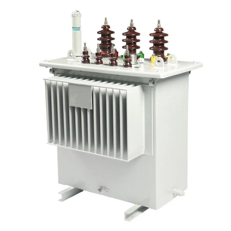
The most straightforward way to prevent oil contamination is to seal the tank from the outside air and design it to withstand the pressures generated by the expanding liquid coolant (Figure 2). Due to the solubility of gas in oil, these pressures remain relatively low and rarely exceed 0.43 kg/cm² under stable load conditions.
The advent of specialized machinery that automatically folds and welds steel plates into deep corrugations for forming the sides of the transformer tank has made corrugated tanks more cost - effective. The steel plates typically range from 1.2 to 1.5 mm in thickness, resulting in a tank that is both lightweight and compact. Its mechanical strength is derived from the closely - spaced, deep corrugations.
Steel plates with widths of up to 2000 mm and depths of 400 mm allow transformers rated up to 5000 kVA to be cooled using this method. However, their typical application is in distribution transformers with ratings up to 1600 kVA.
The flexibility of corrugated panels has led to the development of the fully - sealed corrugated tank design. In this design, the tank is completely filled, and the expansion of the liquid is accommodated by the flexing of the tank walls. The liquid inside the tank has no contact with the atmosphere, which helps preserve the transformer's insulation system and reduces maintenance requirements.
Corrugated transformer tank designs have been in use for over 30 years and are now recognized as a reliable tank - construction method.