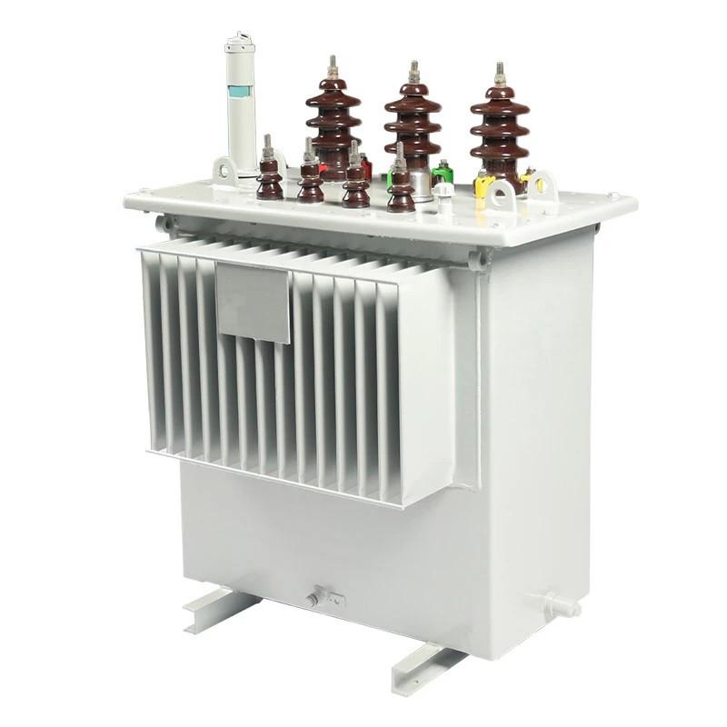
Difference between Power Transformer and Distribution Transformer

Dyson
04/12/2025

Main Differences

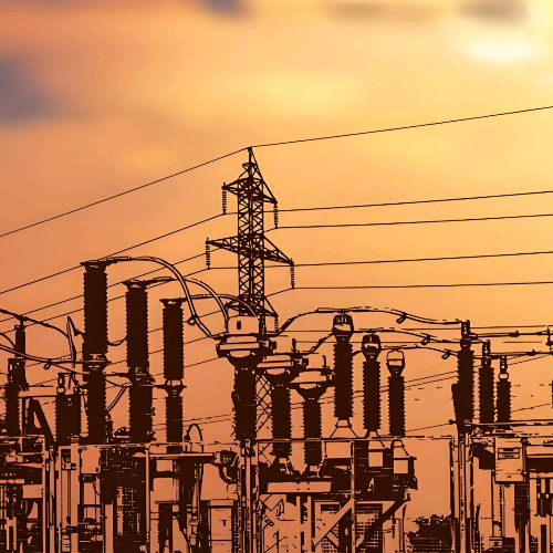
Power transformers are applied in high - voltage transmission networks for step - up and step - down operations (with voltage levels such as 400 kV, 200 kV, 110 kV, 66 kV, 33 kV). Their rated capacity is generally above 200 MVA. In contrast, distribution transformers are utilized in low - voltage distribution networks as a means to connect end - users (with voltage levels such as 11 kV, 6.6 kV, 3.3 kV, 440 V, 230 V). Their rated capacity is usually less than 200 MVA.

Transformer Size / Insulation Level

Power transformers are used for power transmission in heavy - load scenarios with voltages higher than 33 kV, boasting an efficiency of 100%. Compared with distribution transformers, they are larger in size and are applied in power - generating stations and transmission substations, featuring a high insulation level.
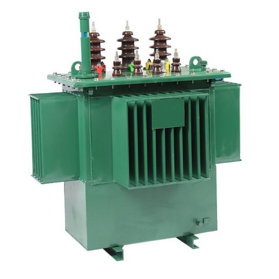
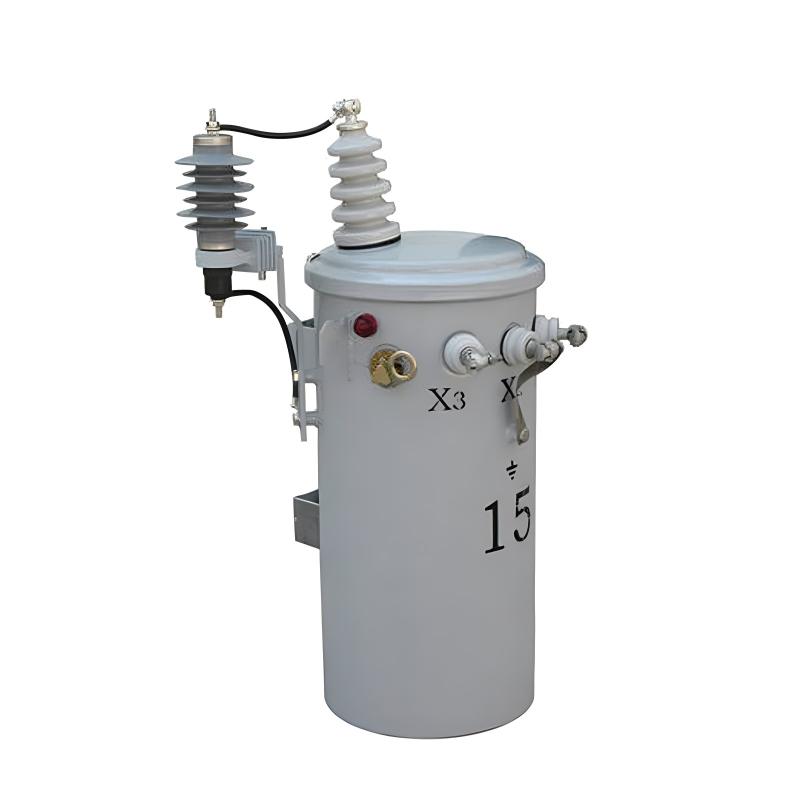
Distribution transformers are used to distribute electrical energy at low voltages, with voltages below 33 kV for industrial applications and 440 V - 220 V for domestic use. They operate at a relatively low efficiency, ranging from 50 - 70%. They are small - sized, easy to install, have low magnetic losses, and do not always operate at full load.

Iron Losses and Copper Losses

Power transformers are used in the transmission network and are not directly connected to consumers, so load fluctuations are minimal. They operate at full load for 24 hours a day, so copper losses and iron losses occur throughout the day, and their specific weight (i.e., iron weight/copper weight) is very low. The average load is close to or at full load, and they are designed to achieve maximum efficiency under full - load conditions. Since they are independent of time, calculating efficiency based solely on power is sufficient.
Distribution transformers are used in the distribution network and are directly connected to consumers, so load fluctuations are significant. They are not always at full load. Iron losses occur 24 hours a day, and copper losses occur based on the load cycle. Their specific weight (i.e., iron weight/copper weight) is relatively high. The average load is approximately 75% of full load, and they are designed to achieve maximum efficiency at 75% of full load. Since they are time - dependent, all - day efficiency is defined to calculate the efficiency.
Power transformers serve as step - up devices in power transmission. This helps minimize I²r losses for a specific power flow. These transformers are engineered to maximize the utilization of the core. They operate close to the knee point of the B - H curve (slightly above the knee - point value), which significantly reduces the mass of the core.Naturally, for power transformers, iron losses and copper losses match at peak load, that is, at the point where maximum efficiency is achieved with equal losses.
Distribution transformers, however, cannot be designed in the same way. Thus, all - day efficiency becomes a key consideration during their design. This depends on the typical load cycle they are meant to supply. The core design must take into account both peak load and all - day efficiency, striking a balance between these two aspects.Power transformers generally operate at full load, so they are designed to minimize copper losses. In contrast, distribution transformers are always online and mostly operate at less - than - full - load conditions. Therefore, they are designed to minimize core losses.
Power transformers function as step - up devices in power transmission, enabling the minimization of I²r losses for a specific power flow. They are designed to optimize core utilization and operate closely to the knee point of the B - H curve (slightly above the knee - point value), thereby greatly reducing the core's mass.
At peak load, these transformers inherently exhibit a balance between iron losses and copper losses, which corresponds to the point of maximum efficiency where the two types of losses are equal.
Distribution transformers, in contrast, cannot be designed in the same manner. Therefore, all - day efficiency is a crucial factor in their design process. This is contingent upon the typical load cycle they are intended to serve. The core design must effectively address both peak load requirements and all - day efficiency, striking a delicate balance between these two aspects.
Power transformers typically operate at full load, so their design focuses on minimizing copper losses. On the other hand, distribution transformers are continuously in operation and mostly function under less - than - full - load conditions. As a result, their design emphasizes minimizing core losses.


Dyson

Focused on the design of electrical equipment, proficient in electrical principles and relevant specifications, and skilled in using design software. From intelligent substations to various types of electrical equipment, I am adept at optimizing design solutions, integrating new technologies. With practical experience and collaborative management capabilities, I deliver outstanding electrical design achievements.

Research on Low - Voltage Anti - DC Current Transformer and Detection Device
1. Overview of Components and IssuesTA (low-voltage current transformer) and electric energy meters are key components of low-voltage electric energy metering. The load current of such meters is no less than 60A. Electric energy meters vary in type, model, and anti-DC performance, and are connected in series in the metering device. Due to the lack of anti-DC capability, they suffer from metering errors under DC component loads, usually caused by non-linear loads. With the increasing use of DC or
Dyson
07/16/2025
Anti - Theft Device for Low - Voltage Current Transformers
1. Innovation BackgroundWith the progress of society and economic development, the electricity demand of power users is expanding increasingly. Lawbreakers, aiming to save electricity costs and pursue high profits, gradually use high - tech methods to steal electricity, causing huge economic losses to power supply enterprises. Currently, popular electricity theft methods in the market include illegally opening the wiring cover of low - voltage transformers in electric energy metering boxes, alte
Dyson
07/16/2025
What aspects should be taken into consideration during the design of AIS voltage transformers?
I. Key Elements of Mechanical Structure DesignThe mechanical structure design of AIS voltage transformers ensures long - term stable operation. For 66 kV outdoor AIS voltage transformers (pillar - type structure):Pillar Material: Use epoxy resin casting + metal frame for mechanical strength, pollution/weather resistance. Special design needed for 66 kV (vs 35 kV & below). Dry - type insulation (porcelain/epoxy shell) requires sufficient bending/impact resistance for harsh outdoors.Heat Dissi
Dyson
07/15/2025
Analysis of Gas Concentration in High - Voltage Reactors of Large - Scale Hydroelectric Generator Sets
1.Gas Generation and Analysis Principle of High - Voltage ReactorsHigh - voltage reactors use oil and insulating paper for insulation. Normal operation may see local overheating or discharges (e.g., iron core/winding issues, inter - turn short circuits), causing insulation cracking and producing gases like hydrocarbons (methane, etc.), CO, CO2, H2). These gases reflect internal insulation status, enabling real - time monitoring.For closed oil - filled reactors, insulation aging and oil oxidation
Oliver Watts
07/11/2025
Inquiry
Download
IEE-Business is dedicated to serving the personnel in the global power industry.
Join IEE-Business, not only can you discover power equipment and power knowledge, but also canhnd like - minded friends!