This paper aims to explore the insulation failure mechanisms and safety boundaries of Dead Tank (DT) and Live Tank (LT) circuit breakers from the perspectives of dielectric physics and electrical stress.
1. Dependence on Dielectric Media: Endogenous Variables of Sealed Systems vs. Environmental Variables of Open Systems
The fundamental distinction between DT and LT designs lies in the degree to which their primary insulation media depend on external conditions.
1.1 Dead Tank (DT): State-Dependent Insulation Based on SF6 Density
The core insulation medium of a DT breaker is SF6 gas. Its dielectric strength is not a constant value but is strongly and positively correlated with gas density (pressure × purity). This dictates that the insulation level of a DT breaker is a dynamic variable:
- Pressure Sensitivity: As gas pressure drops, the breakdown field strength undergoes non-linear attenuation. Once pressure falls below a critical threshold, the insulation margin collapses rapidly.
- Chemical Stability: Increased moisture content leads to hydrolysis, generating corrosive substances like HF (hydrogen fluoride) while simultaneously reducing surface flashover voltages.
- Particle Effects: The movement of internal metallic particles under the influence of an electric field is a primary trigger for local field distortion, eventually leading to breakdown. Consequently, the insulation safety of a DT breaker is predicated on the rigid requirement of "sealed system integrity," representing an endogenous risk.
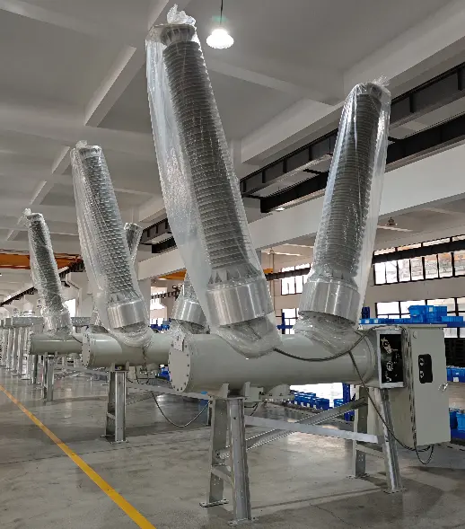
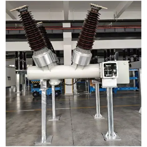
Physical Photo of RHD-230 Dead-Tank SF6 Circuit Breaker
1.2 Live Tank (LT): Environment-Dependent Insulation Based on Air and Solids
LT breakers rely on air gaps and porcelain/composite insulators (solid insulation) for dielectric strength. Their dielectric baseline is determined by ambient atmospheric conditions:
- Constant Baseline: Air insulation does not rely on a sealed environment; thus, there is no risk of insulation failure due to medium leakage.
- Surface Characteristics: The insulation level is primarily limited by the creepage distance and atmospheric conditions (humidity, pollution). While pollution flashover is the primary risk, it is an exogenous risk that develops slowly and is usually observable (e.g., tracking marks, audible discharge).
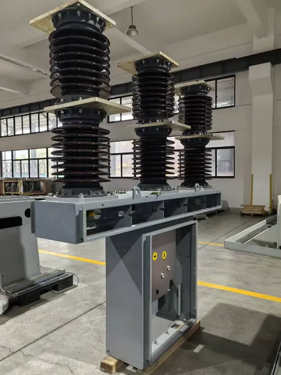
Physical Photo of RHB-40.5 Live-Tank SF6 Circuit Breaker
2. The Electrical Essence of Breakdown Paths: Natural Disparities in External Insulation Distance
The simplified assumption of "breakdown endpoint identity" (that both eventually ground) requires precise physical correction. Although the ultimate electrical reference point for both is ground potential, the insulation distance from the high-voltage energized components to the ground (and personnel activity areas) differs fundamentally.
2.1 The Geometric Advantage of LT: High-Level Placement and Long Creepage Paths
The structure of an LT breaker dictates that its high-voltage components (interrupters and conductors) are positioned at a significant height, isolated from the ground by long support insulators. This design provides an objective insulation margin:
- Air Clearance Advantage: The clearance from high-voltage terminals to the ground is significantly greater in LT than in DT. Even if an external flashover occurs, the arc channel originates at a high altitude, and the direct electrocution risk to personnel (touch/step voltage) is significantly diluted by the inverse-square law of distance.
- External Insulation Dominance: LT insulation failure typically manifests as external air gap breakdown or surface flashover. Because the dielectric (air) is open and self-healing, and the fault path is far from the ground, the coupling effect of Ground Potential Rise (GPR) is relatively weak. The hazard is primarily thermal radiation and shockwaves from the arc rather than a direct back-strike through the grounding system.
2.2 The Geometric Constraints of DT: Low-Level Placement and Short Gaps
In a DT design, the high-voltage conductor is encapsulated within a grounded metallic tank located very close to the ground.
- Media Substitution Distance: DT breakers sacrifice physical air distance in exchange for the high dielectric strength of SF6. However, if gas pressure is insufficient or internal insulation degrades, the short distance between the high-voltage conductor and the tank shell (ground) means the breakdown risk acts directly upon ground-level equipment.
- GPR-Dominated Risk: Any insulation breakdown in a DT breaker (whether internal conductor-to-tank or bushing-to-flange) manifests as a direct short circuit to the grounded metal enclosure. The fault current, without the attenuation provided by a long air path, is injected directly into the grounding grid, causing a violent and instantaneous rise in the potential of the tank and surrounding surface (GPR). This low-impedance, proximity-based GPR is the most direct and lethal threat to personnel.
3. Defining Safety Boundaries
3.1 The DT Safety Boundary: Media State and Mechanical Strength
The safety boundary for a DT breaker is defined by two factors:
- Dielectric Boundary: The SF6 density-temperature curve. Once the operating point falls below the minimum functional pressure, the insulation safety boundary is breached.
- Structural Boundary: The mechanical strength of the tank and its pressure relief channels. An Internal Arc Fault (IAC) is the most severe insulation failure mode for DT; the energy release is confined by the metal vessel and must be directed through preset relief vents to prevent structural disintegration.
3.2 The LT Safety Boundary: External Insulation Level and Surface Field Strength
The safety boundary for an LT breaker depends primarily on:
- Air Clearance: Adherence to standardized Basic Insulation Levels (BIL) and Switching Insulation Levels (SIL). Due to its high-level placement, its safety margin is generally higher than the ground clearance of a DT breaker of the same voltage class.
- Creepage Distance: The length of the insulator surface designed for specific pollution levels.
- Dry/Wet Flashover Voltage: In adverse weather, the breakdown field strength of the air gap decreases, forming the weak link in the safety boundary.
4. Conclusion
From a pure insulation design perspective, DT and LT breakers represent two distinct risk control philosophies, with objective differences in ground-level insulation margins:
- LT breakers possess a natural external insulation advantage: By placing high-voltage components at a high altitude, they utilize air distance as the primary safety barrier for ground personnel. Insulation failures are mostly visible external flashovers, and the threat of GPR is diluted by distance.
- DT breakers rely on artificial media compensation: To compensate for the lack of insulation distance caused by ground-level placement, high-strength SF6 gas must be used. This makes insulation safety highly dependent on the state of the medium (pressure, purity). Should a breakdown occur, the energy acts directly on the grounding system, posing a significantly higher electrocution risk to ground personnel compared to LT breakers.
Refined Conclusion: The argument that "the risk is identical because the breakdown endpoint is the same" is flawed. LT breakers, through their high-altitude configuration, possess a natural margin in external insulation that DT breakers cannot replicate. The inherent risk of DT lies in the fact that once the internal insulation (SF6 system) fails, the fault energy strikes the ground-level safety boundary without any buffer.
Edited From:ChengMing Chen

 Login