Design and Application of Three-Phase Mechanical Linkage for 252kV Tank-Type SF₆ Circuit Breakers in China's High-Voltage Power Grid
In China's high-voltage transmission network, three-phase power transmission systems are universally adopted, with high-voltage electrical equipment also configured in three-phase layouts. Most existing 252kV tank-type SF₆ circuit breakers feature phase-separated designs, where each phase is equipped with an independent motor-spring operating mechanism. Three-phase mechanical interlocking is achieved through electrical linkages via a junction control box. However, electrical linkages are susceptible to external influences, often leading to issues such as non-full-phase operation and poor three-phase switching synchronization. These problems pose significant impacts on power grid stability due to increased surge stresses on transmission lines. To address these challenges and enhance operational reliability, a three-phase mechanical linkage structure has been developed to ensure synchronized drive by a single mechanism, thereby improving three-phase synchronization and preventing phase-loss faults.
Design Scheme
Contrast Between Electrical and Mechanical Linkages
Three-Phase Electrical Linkage: Utilizes three independent operating mechanisms (e.g., CT20 motor-spring mechanisms for LW24-252 products), with interphase coordination achieved through electrical connections in the junction box. Each phase’s drive shaft directly connects to its respective arc-quenching chamber. Protection systems employ three-phase position mismatch relays to trigger tripping.
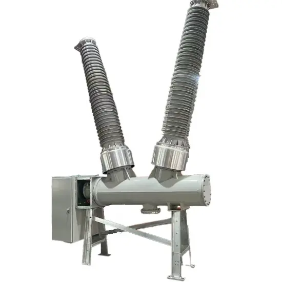
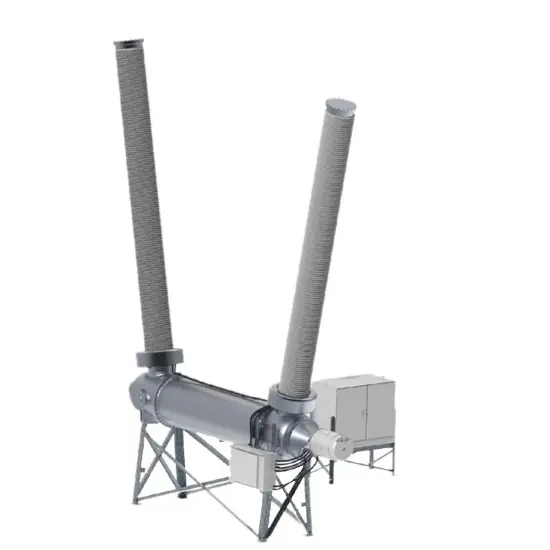
Three-Phase Mechanical Linkage: Employs a single hydraulic-spring operating mechanism, with the three-phase arc-quenching chambers linked via mechanical connecting rods. For 252kV tank-type circuit breakers with horizontal arc-quenching chamber layouts (common in outdoor substations), the operating mechanism and drive system are positioned in front of the chambers, requiring re-optimized design for mechanism mounting, drive trains, and support structures.
Retrofit of LW24-252 Circuit Breakers
The original LW24-252 features phase-separated operation with three CT20 mechanisms. To achieve mechanical linkage:
Upgraded Operating Mechanism: Replaced with a high-power hydraulic-spring mechanism (e.g., CYA5-5) to meet the increased operational energy requirements (calculated single-phase switching energy necessitates a robust hydraulic design).
Seal Structure Improvement: Converted from direct-acting seals (using compressed PTFE V-gaskets with high friction and cost) to rotary lip seals for reduced operating force and improved reliability.
Rigid Interphase Fixing: Installed connecting plates to maintain interphase spacing and enhance drive rigidity.
Dual-Tie Rod System: Employed dual tie rods to transmit torque and prevent deformation during switching, ensuring synchronized movement.
Integrated Mechanism Box: Redesigned to accommodate the single hydraulic mechanism, streamlining control and mechanical interfaces.
Working Principle and Structure
The hydraulic-spring mechanism drives a piston rod in linear motion, which is converted to rotational motion via a drive crank arm. This motion is transmitted through tie rods to synchronize the three phases. A crank arm box then converts rotational motion back to linear motion to actuate the moving contacts within the arc-quenching chambers.
Closing Process: The piston rod moves rightward, driving the crank arm to rotate the drive shaft counterclockwise. This motion is transferred via tie rods to all three phases, pushing the internal tie rods inward until the contacts close fully.
Opening Process: Motions are reversed, with the piston rod retracting to pull the contacts apart.
Strength Design of Drive Components
To maintain original mechanical characteristics under three-phase linkage, the hydraulic-spring mechanism’s high operational energy (e.g., 10,000J total switching energy) necessitates reinforced crank arms and tie rods. Finite element analysis ensures stress distribution within material limits during high-energy operations.
Mechanism Selection and Debugging
Hydraulic-Spring Mechanism Features
Advantages: Compact design, high integration, large operating energy (2540J for closing, 10005J for tripping), minimal temperature impact, and high reliability.
Technical Parameters:
Rated operation cycle: Open - 0.3s - Close-open - 180s - Close-open
Rated oil pressure: 48.7MPa ±3MPa
Energy storage time: ≤60s per cycle
Mechanical life: 5000 cycles (M2 grade: 10,000 cycles)

Debugging and Performance
Energy Matching: The CYA5-5 mechanism (10,000J total energy) meets the 252kV circuit breaker’s requirements (6500J for tripping, 3500J for closing), with safety margins ensured.
Synchronization: Three-phase switching synchronization is improved to ≤3ms (vs. conventional LW24-252’s 3ms baseline), achieved through hydraulic flow regulation in solenoid valves.
Cost Efficiency: Replacing three separate mechanisms with one reduces costs by ~15% (85% of conventional phase-separated designs) while increasing sales value by 1.5x due to enhanced reliability.
Type Testing
Conclusion
The developed three-phase mechanical linkage system for 252kV tank-type SF₆ circuit breakers addresses critical reliability issues in high-voltage grids. By eliminating phase synchronization errors and reducing component count, this innovation enhances grid stability while achieving cost savings. With international leading technical standards and independent intellectual property rights, this solution fills a domestic technological gap, providing robust equipment support for China’s power grid expansion and offering broad market prospects, including potential applications in hybrid switchgear systems.