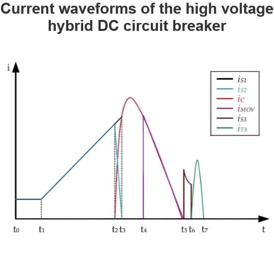
The Figure Shows the Current and Voltage Waveforms. When the DCCB (Direct Current Circuit Breaker) is in Normal Operation (Circuit Breaker S1 and Residual Current Circuit Breaker S2 are Closed, S3 is Open), the Opening Sequence Begins. The Circuit Breaker is Triggered by a Protective Relay. Here, the Relay Time is Assumed to be 2ms. After Receiving the Trip Signal, Switch S1 Starts to Operate. When It Reaches a Sufficient Distance to Withstand the Transient Voltage Applied During the Interruption, the Resonant Circuit Injects Reverse Current by Closing Switch S3. This Creates a Current Zero Point in the Circuit Breaker (S1), and All Current Now Flows Through the Resonant Branch, Causing the Capacitor Voltage to Rise. When the Capacitor Voltage Reaches the Clamping Voltage of the Surge Arrester (SA), the Current Through the Circuit Breaker Begins to Rapidly Decrease.
The Total Time from Receiving the Trip Signal to Generating the Reverse Voltage is Approximately 8ms, Considering Mechanical Activation and Current Commutation.
Then, the Energy Stored in the System Dissipates in the Surge Arrester (SA), Depending on the System Conditions.
Detailed Steps
Normal Operation State:
Circuit Breaker S1 and Residual Current Circuit Breaker S2 are closed.
High-Speed Switch S3 is open.
Opening Sequence Begins:
The protective relay detects a fault and sends a trip signal, assuming a relay time of 2ms.
Switch S1 Operates:
After receiving the trip signal, the high-speed mechanical circuit breaker S1 starts to operate.
When S1 reaches a sufficient distance to withstand the transient voltage applied during the interruption, the resonant circuit is ready.
Injection of Reverse Current:
The resonant circuit injects reverse current by closing the high-speed switch S3.
This creates a current zero point in the circuit breaker S1, and all current begins to flow through the resonant branch, causing the capacitor voltage to rise.
Rapid Current Reduction:
When the capacitor voltage reaches the clamping voltage of the surge arrester (SA), the current through the circuit breaker S1 begins to rapidly decrease.
Energy Dissipation:
The total time from receiving the trip signal to generating the reverse voltage is approximately 8ms, including mechanical activation and current commutation.
The energy stored in the system dissipates in the surge arrester (SA), depending on the system conditions.
Through this sequence of steps, the DCCB can effectively interrupt the current and protect the system from fault conditions.
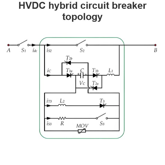
Component Detail
S1: High-Speed Mechanical Circuit Breaker
S2: Residual Current Circuit Breaker
S3: High-Speed Switch
SA: Surge Arrester