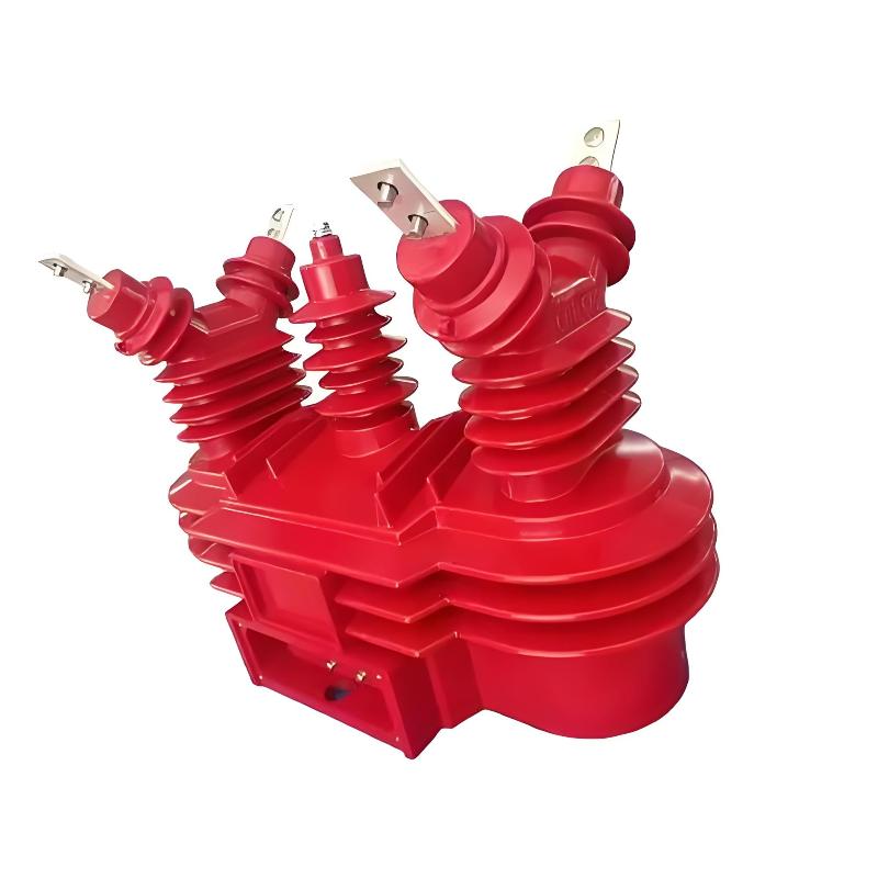
What are the fault diagnosis and handling technologies for 35kV combined transformers?

Felix Spark
07/21/2025

For fault diagnosis and handling of 35kV combined transformers, the following technical means can be adopted:
Insulation Fault Diagnosis
Use equipment such as high-voltage test transformers, power frequency withstand voltage testers, and partial discharge detection systems to conduct a comprehensive assessment of the insulation performance of combined transformers. When the insulation resistance is found to be lower than 1000MΩ or the dielectric loss factor tanδ exceeds 0.5%, an application for shutdown and maintenance should be made immediately. For SF₆ equipment, the presence of gas leakage can be determined using an infrared leak detector or a pressure monitoring system.
Ferromagnetic Resonance Diagnosis
Identify the presence of resonance by analyzing changes in zero-sequence voltage (3U₀) and three-phase voltage unbalance through fault recording. When 3U₀ voltage is found to gradually increase or three-phase voltages are severely unbalanced, the possibility of ferromagnetic resonance should be considered. In addition, the risk of resonance can be assisted in judgment by monitoring changes in system parameters (such as the ratio of capacitive reactance to inductive reactance) and operation records (such as ground recovery and switching operations).
Electromagnetic Interference Diagnosis
Use electromagnetic compatibility testing equipment to evaluate the electromagnetic compatibility performance of combined transformers. Methods such as monitoring partial discharges via capacitive coupling, detecting discharge locations with ultrasonic waves, and observing abnormal temperature rises through infrared thermal imaging can identify the degree of influence of electromagnetic interference. For combined transformers in a GIS environment, it is also necessary to monitor the intrusion of high-frequency transient electromagnetic waves into low-voltage acquisition units.
Mechanical Vibration Diagnosis
Use acceleration sensors to monitor vibration waveforms and identify abnormal frequencies through spectrum analysis. By comparing with standard vibration signals, it can be judged whether there is vibration caused by partial discharge or mechanical structural looseness. In addition, infrared temperature measurement can also help detect local overheating caused by poor contact due to vibration.
Secondary Circuit Fault Diagnosis
Check the status of secondary fuses, measure the resistance of secondary circuits, and observe abnormal instrument indications. When a secondary fuse of a certain phase is found to be blown, check whether the indications of the voltmeter, power meter, etc. of that phase are reduced; if an open circuit in the secondary circuit is found, it will be accompanied by a loud "buzzing" sound and abnormal instrument indications, and power should be cut off for processing in a timely manner. In addition, partial discharge measurement can also detect discharge phenomena caused by abnormalities in the secondary circuit.
Calibration and Load-Related Fault Diagnosis
Use a three-phase calibration system to apply three-phase voltage and current simultaneously, simulate actual working conditions, and evaluate the measurement performance of the combined transformer. By comparing the error differences between the single-phase method and the three-phase method, the degree of influence of electromagnetic interference on measurement accuracy can be judged. In addition, infrared temperature measurement can also monitor abnormal temperature rises caused by overload.
SF₆ Gas Leakage Diagnosis
Use equipment such as infrared imaging leak detectors, wavelet analysis signal processing systems, and pressure monitoring devices to conduct a comprehensive assessment of the sealing performance of SF₆ equipment. Infrared imaging leak detection can visually locate leak points, while wavelet analysis can improve detection accuracy, making it suitable for monitoring micro-leaks. For SF₆ equipment with severe leaks, it should be immediately taken out of operation for maintenance.
Felix Spark

Hey there! I'm an electrical engineer specializing in Failure and Maintenance. I've dedicated my career to ensuring the seamless operation of electrical systems. I excel at diagnosing complex electrical failures, from malfunctioning industrial motors to glitchy power distribution networks. Using state - of - the - art diagnostic tools and my in - depth knowledge, I pinpoint issues quickly. On this platform, I'm eager to share my insights, exchange ideas, and collaborate with fellow experts. Let's work together to enhance the reliability of electrical setups.

What Tests Are Required for a Qualified Combined Instrument Transformer?
Hi everyone, I’m Oliver, and I’ve been working in the instrument transformer industry for almost eight years now. From a complete newbie to someone who can now handle things independently, I’ve participated in dozens of combined instrument transformer inspections over the years.Today, I’d like to share with you: What tests must a qualified combined instrument transformer go through before leaving the factory or being put into operation? After all, it's a very critical pie
Oliver Watts
07/21/2025
What are the applications and trends of 35kV combined transformers?
Applications and Trends of 35kV Combined Instrument Transformers – From Echo’s PerspectiveHey everyone! My name is Echo, and I’ve been working in the field of instrument transformers for 12 years now. Today, I’d like to share some insights about the applications and future trends of 35kV combined instrument transformers. Hope this can give you a glimpse into this fascinating industry.Application Scenarios: More Than Just Metering ToolsFirst off, let's talk about applicati
Echo
07/21/2025
Development of Medium - Voltage Combined Electronic Transformers
1 Measurement Principle of Combined Electronic Transformers1.1 Voltage Measurement PrincipleElectronic transformers measure voltage using the capacitive voltage division method. Since the voltage across a capacitor cannot change abruptly, the secondary voltage obtained directly through capacitive voltage division has poor transient response and low measurement accuracy. To improve the measurement accuracy, a precision sampling resistor is connected in parallel across the low-voltage capacitor. I
Dyson
07/21/2025
Combined Voltage Transformer Secondary Circuit Overvoltage Suppression Technology
This paper analyzes the above situation in - depth and summarizes technical measures to solve the problems.1. Main Problems of SPD Products in Voltage Transformer Secondary CircuitsCurrently, there are residual - current - free SPDs (switch - type lightning arresters) at home and abroad. Their main internal discharge circuits use discharge tubes/gaps, with high discharge current capacity (exceeding zinc oxide varistors). However, they have fatal flaws: poor voltage - limiting, arc - pulling volt
Dyson
07/21/2025
Inquiry
Download
IEE-Business is dedicated to serving the personnel in the global power industry.
Join IEE-Business, not only can you discover power equipment and power knowledge, but also canhnd like - minded friends!