1 Measurement Principle of Combined Electronic Transformers
1.1 Voltage Measurement Principle
Electronic transformers measure voltage using the capacitive voltage division method. Since the voltage across a capacitor cannot change abruptly, the secondary voltage obtained directly through capacitive voltage division has poor transient response and low measurement accuracy. To improve the measurement accuracy, a precision sampling resistor is connected in parallel across the low-voltage capacitor. Its principle is shown in Figure 1.

In Figure 1, under the condition that


The output voltage of the voltage - dividing capacitor is proportional to the time - derivative of the measured voltage. By adding an integration link, the primary voltage can be measured.
In Figure 1, since most of the voltage drop occurs across C1, there are very high requirements for the insulation of capacitor C1. In electromagnetic voltage transformers, power capacitors are generally used, while in electronic voltage transformers, power capacitors are not used; instead, equivalent capacitors are adopted.
The structure of the voltage - dividing capacitor is that an insulating - material - made cylinder is sleeved on a conductive rod. Then, a double - layer flexible circuit board is attached to the outside of the cylinder. The precision resistor is a chip resistor attached to the outer layer of the flexible circuit board. The structural schematic diagram of the capacitor voltage divider is shown in Figure 2.

The capacitance of C1 is formed by the inner - layer cylinder. The conductive rod is equivalent to one electrode plate, and the inner copper film of the flexible circuit board is equivalent to the other electrode plate, with the insulating material as the dielectric. The capacitance of C2 is formed by the outer - layer cylinder. The double - sided copper films of the double - layer flexible circuit board are equivalent to the electrode plates, and the base material of the flexible circuit board, such as polyimide, serves as the dielectric. Its radial cross - sectional view is shown in Figure 3.The equivalent capacitance C can be calculated by Formula.

In formula: r1 is the inner radius of the cylinder; r2 is the outer radius of the cylinder; H is the length of the flexible printed circuit board; εr is the relative permittivity of the electrolyte; ε0 is the vacuum permittivity.

1.2 Current Measurement Principle
Electronic transformers use Rogowski coils to measure current. The relationship between the secondary output voltage and the primary input current is as follows:

In the formula, M is a constant irrelevant to the position of the measured current. The output voltage of the Rogowski coil is proportional to the derivative of the measured current. Therefore, by adding an integration link after the output of the Rogowski coil, the measured current can be restored.
In this project, the Rogowski coil is a Rogowski coil made of a printed circuit board. Its sensitivity, measurement accuracy, performance stability, product interchangeability, and production efficiency are all superior to those of traditionally wound coils.
To reduce the interference of the accessory magnetic field and improve the measurement accuracy, the Rogowski coil made of a printed circuit board generally uses two coils connected in series to form a differential input. The winding directions of these two PCB coils are different. One is wound according to the right - hand rule, and the other is wound according to the left - hand rule. In this way, two induced voltages with opposite polarities are generated, and the output voltage of the series connection is twice that of a single Rogowski coil, as shown in Figure 4.

1.2 Current Measurement Principle (Continued)
Due to the different thermal expansion coefficients of the copper film and the PCB substrate, their deformation amounts differ when the temperature changes. To reduce errors caused by deformation and prevent copper film breakage, the manufactured PCB coils undergo a temperature aging process. This process, on one hand, releases the coils' internal stress to minimize errors and, on the other hand, serves to screen the coils.
Although Rogowski coils with differential output have strong common - mode suppression capability, the 10 kV electric field interference remains significant. Therefore, it is necessary to wrap the Rogowski coils with copper foil and ground the copper foil.
2 Composition Principle of Combined Electronic Transformers
2.1 Composition Block Diagram of Combined Electronic Transformers
The block diagram of the combined electronic transformer is shown in Figure 5. The primary voltage and current are converted into secondary signals by the capacitor and the Rogowski coil. By integrating and shifting the phase of the secondary signals, signals proportional to the primary signals can be obtained. To improve accuracy, the integration and phase compensation of measurement signals can be achieved through digital signal processing methods. However, digital signal processing has a certain delay and cannot reflect the primary signals in real - time. Thus, this processing method is not suitable for protection signals. Since protection signals have lower requirements for measurement accuracy, analog circuits can be directly used for amplification, integration, and phase compensation processing.

2.2 Structure of the Sensing Head of the Combined Electronic Transformer
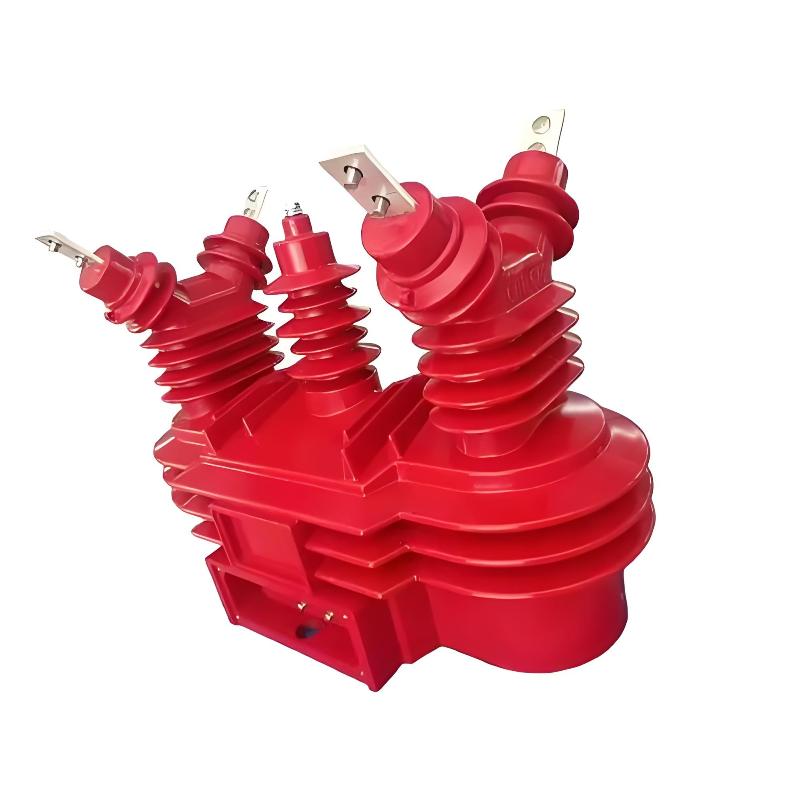
The combined electronic transformer encapsulates the voltage measurement unit and the current measurement unit into the structure shown in Figure 6 using epoxy resin vacuum casting.
The Rogowski coil is cast onto the current - carrying busbar. After amplification, the coil output signal is sent to the output terminal via a signal line. Since the amplifier requires a dual power supply, 3 of the multi - core signal lines are used for power transmission.
As there is no current flowing through the conductive rod of the voltage transformer, and to increase the creepage distance, a structure where the conductive rod and the current - carrying busbar are perpendicular to each other is adopted.
Because the sensing head is of an active type, the service life of electronic components severely restricts the service life of the electronic transformer sensing head. Therefore, all components must undergo aging screening before use.
To improve the signal - to - noise ratio, current and voltage signals are amplified inside the sensing head. The amplification circuit for the current signal is on the PCB coil, and the amplification circuit for the voltage signal is on the flexible circuit board. High - performance instrumentation amplifiers are used for the amplifiers.
3 Testing of the Combined Electronic Transformer
In accordance with the above - mentioned principles and structure, as well as the IEC 60044 - 7 and IEC 60044 - 8 standards, a 10 kV/600 A integrated voltage/current electronic transformer prototype has been designed. For the voltage transformer, the measurement accuracy is Class 0.5, and the protection level is 3P; for the current transformer, the measurement accuracy is Class 0.2, and the protection accuracy is 5P20.
During the test, different currents are passed through the electronic transformer and different voltages are applied to it. The secondary output is output through a digital port. After being displayed by the digital display unit, it is compared with the reference current transformer and the reference voltage transformer. Its measurement accuracy meets the design requirements.
At the same time, power frequency withstand voltage, partial discharge, lightning impulse, and electromagnetic compatibility tests are carried out on the prototype. The passing of these tests indicates the correctness of the design scheme.

4 Conclusions
(1) Using a voltage - dividing capacitor composed of equivalent capacitors and a Rogowski coil made with a printed circuit board as voltage and current sensors, it has a simple structure, good product interchangeability, and high measurement accuracy.
(2) By adopting printed circuit board and flexible printed circuit board technologies, the amplification circuit can be built inside the sensing head, improving the signal - to - noise ratio of the measurement signal.
(3) Combining the electronic voltage transformer and the electronic current transformer into one to form a combined voltage - current transformer can not only reduce the cost of primary equipment but also improve the accuracy and capacity of the secondary circuit for the voltage of a single line. It meets the new requirements for secondary metering and protection and also conforms to the control concept of modern power systems that takes switchgear intervals as units.