• Product
  • Suppliers
  • Manufacturers
  • Solutions
  • Free tools
  • Knowledges
  • Experts
  • Communities
Search


Op amp ope Operational Amplifier

Electrical4u
Electrical4u
Larangan: Basic Electrical Basikong Elektikal
0
China

An operational amplifier or op amp is a DC coupled voltage amplifier with a very high voltage gain.

Op amp is basically a multistage amplifier in which a number of amplifier stages are interconnected to each other in a very complicated manner. Its internal circuit consists of many transistors, FETs and resistors. All this occupies a very little space.
So, it is packed in a small package and is available in the
Integrated Circuit (IC) form. The term Op Amp is used to denote an amplifier which can be configured to perform various operations like amplification, subtraction, differentiation, addition, integration etc. An example is the very popular IC 741.

The symbol and its actual appearance in the IC form is shown below. The symbol appears as an arrowhead which signifies that the signal is flowing from output to input.op-ampsymbol of op-amp

Input and Output Terminals of an Operational Amplifier

An op-amp has two input terminals and one output terminal. The op-amp also has two voltage supply terminals as seen above. Two input terminals form the differential input. We call the terminal, marked with negative (-) sign as the inverting terminal and the terminal marked with positive (+) sign as the non-inverting terminal of the operational amplifier. If we apply an input signal at the inverting terminal (-) than the amplified output signal is 180o out of phase concerning the applied input signal. If we apply an input signal to the non-inverting terminal (+) then the output signal obtained will be in phase, i.e. it will have no phase shift concerning the input signal.

Power Supply for an Operational Amplifier

As seen from the circuit symbol above it has two input power supply terminals +VCC and –VCC. For the operation of an op-amp a dual polarity DC supply is essential. In the dual polarity supply, we connect the +VCC to the positive DC supply and the –VCC terminal to the negative DC supply. However few op-amps can also operate on a single polarity supply. Note that there is no common ground terminal in the op-amps hence the ground has to be established externally.

Working Principle of Op-Amp

Open Loop Operation of an Operational Amplifier

As said above an op-amp has a differential input and single ended output. So, if we apply two signals one at the inverting and another at the non-inverting terminal, an ideal op-amp will amplify the difference between the two applied input signals. We call this difference between two input signals as the differential input voltage. The equation below gives the output of an operational amplifier.Where, VOUT is the voltage at the output terminal of the op-amp. AOL is the open-loop gain for the given op-amp and is constant (ideally). For the IC 741 AOL is 2 x 10⁵.
V1 is the voltage at the non-inverting terminal.
V2 is the voltage at the inverting terminal.
(V1 – V2) is the differential input voltage.
It is clear from the above equation that the output will be non-zero if and only if the differential input voltage is non-zero (V1 and V2 are not equal), and will be zero if both V1 and V2 are equal. Note that this is an ideal condition, practically there are small imbalances in the op-amp. The open-loop gain of an op-amp is very high. Hence, an open loop operational amplifier amplifies a small applied differential input voltage to a huge value.
Also, it is true that if we apply small differential input voltage, the operational amplifier amplifies it to a considerable value but this significant value at the output cannot go beyond the supply voltage of the op-amp. Hence it does not violate the law of conservation of energy.

Closed Loop Operation

The above-explained operation of the op-amp was for open-loop i.e. without a feedback. We introduce feedback in the closed loop configuration. This feedback path feeds the output signal to the input. Hence, at the inputs, two signals are simultaneously present. One of them is the original applied signal, and the other is the feedback signal. The equation below shows the output of a closed loop op-amp.Where VOUT is the voltage at the output terminal of the op-amp. ACL is the closed loop gain. The feedback circuit connected to the op-amp determines the closed loop gain ACL. VD = (V1 – V2) is the differential input voltage. We say the feedback as positive if the feedback path feeds the signal from the output terminal back to the non-inverting (+) terminal. Positive feedback is used in oscillators. The feedback is negative if the feedback path feeds the part of the signal from the output terminal back to the inverting (-) terminal. We use negative feedback to the op-amps used as amplifiers. Each type of feedback, negative or positive has its advantages and disadvantages.

Positive Feedback ⇒ Oscillator
Negative Feedback ⇒ Amplifier

The above explanation is the most basic working principle of operational amplifiers.

Ideal Op-Amp Characteristics

An ideal op-amp should have the following characteristics:

  1. Infinite voltage gain (So that maximum output is obtained)

  2. Infinite input resistance (Due to this almost any source can drive it)

  3. Zero output 

Maghatag og tip ug pagsalig sa author
Gipareserbado
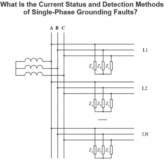
Unsa ang Kasamtangan nga Status ug mga Paraan sa Pagtukod sa mga Pagsalig sa Yuta sa Single-Phase?
Kasamtangan sa Pagdiskubre sa Single-Phase Grounding FaultAng mababang akurasiya sa pagdiskubre sa single-phase grounding fault sa mga sistema nga dili efektibong gipundok sa ground mahimong ipasabot sa daghang mga paktor: ang nagbabagyo nga struktura sa mga distribution network (tulad sa looped ug open-loop configurations), ang iba't ibang mga modo sa system grounding (kasama ang ungrounded, arc-suppression coil grounded, ug low-resistance grounded systems), ang kasinatian nga taasan sa annual
Leon
08/01/2025
Metodo sa paghatag og bahin sa pako para sa pagsukol sa mga parametro sa insulasyon gikan sa grid ngadto sa yuta
Ang metodo sa pagbahin sa frequency nagpadayon sa pagsukat sa mga parametro gikan sa grid hangtod sa yuta pinaagi sa pagbutang og kasiguro nga signal sa kaunting frequency sa open delta side sa potential transformer (PT).Kini nga metodo ang gamiton sa mga sistema nga walay grounding; nganong, sa pagsukat sa mga parametro gikan sa grid hangtod sa yuta sa usa ka sistema diin ang neutral point adunay grounding pinaagi sa arc suppression coil, ang arc suppression coil kinahanglan i-disconnect sa ope
Leon
07/25/2025
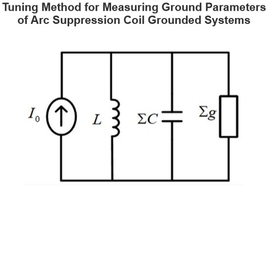
Metodo sa Pagtunaw para sa Pagsukat sa Ground Parameters sa Arc Suppression Coil Grounded Systems
Ang paraan sa pagtunug ay angkop sa pagsukat sa mga parametro sa lupa para sa mga sistema diin ang neutral point adunay grounding pinaagi sa arc suppression coil, apan dili angkop sa mga sistema nga walay grounding sa neutral point. Ang prinsipyo sa pagsukat niana mao ang pag-inject og current signal nga may continuously varying frequency gikan sa secondary side sa Potential Transformer (PT), pagsukat sa returned voltage signal, ug pag-identify sa resonant frequency sa sistema.Sa panahon sa pros
Leon
07/25/2025
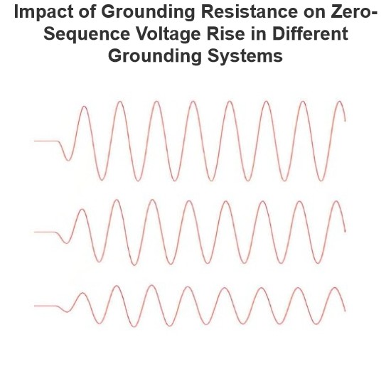
Ang Epekto sa Pagtaas sa Voltage sa Zero-Sequence sa Diferenteng mga Sistema sa Grounding nga Nagdulot ang Resistance sa Grounding
Sa usa ka sistema nga nagpadala og arko-suppression coil sa ground, ang pagtaas sa zero-sequence voltage dako kaayo ang maapektuhan pinaagi sa value sa transition resistance sa grounding point. Ang mas dako ang transition resistance sa grounding point, ang mas sayon ang pagtaas sa zero-sequence voltage.Sa usa ka ungrounded system, ang transition resistance sa grounding point wala bisan unsa nga epekto sa pagtaas sa zero-sequence voltage.Simulation Analysis: Arc-suppression Coil Grounding SystemS
Leon
07/24/2025
Inquiry
Pangutana
Pangutana sa IEE-Business Application
Pangita og mga equipment gamit ang IEE-Business app asa asa ug kailan man sugad og pagkuha og solusyon pagsulay sa mga eksperto ug pagpadayon sa industriya nga pakisayran suportahan ang imong proyekto sa kuryente ug negosyo