• Product
  • Suppliers
  • Manufacturers
  • Solutions
  • Free tools
  • Knowledges
  • Experts
  • Communities
Search


Single and Multi Mesh Analysis

Electrical4u
Field: Basic Electrical
0
China

The word mesh means a smallest loop which is closed one and formed by using circuit components. The mesh must not have any other loop inside it.

mesh

Like the other network analysis procedures, we can use Mesh Analysis to find out the voltage, current or power through a particular element or elements. Mesh analysis is based on Kirchhoff Voltage Law. We can use Mesh analysis only on planar circuits. The planar circuit is the one which is possible to draw on a plane surface in such a way that no branch passes over or under any other branch. This circuit does not contain any branch which passes over or under any other branch.

Single Mesh

If in a closed circuit the number of mesh is only one, then that types of circuits are known as single meshed circuits.

single mesh

In these types of analysis, the current or voltage across any element can be found out directly by using Ohm’s law. However, if the circuit elements are in parallel then also we can convert them into a single mesh by using the law of parallel combinations of the circuit elements.

Multi Mesh

The circuit, which has more than one mesh, is known as multi meshed circuit. The analysis of multi meshed circuit is somewhat difficult as compared to that of single meshed circuit.

multi mesh circuit

If you would prefer a video explanation, we go over an example in the video below:

Steps for Mesh Analysis

The steps followed in mesh analysis are very simple, they are as follows-

  1. Frst we have to determine whether the circuit is planar or non planar. If it is a non planar circuit, we have to perform other methods of analysis such as nodal analysis.

  2. Then we have to count the number of meshes. The number of equations to be solved is same as the number of meshes.

  3. Then we label each of the mesh currents according to the convenience.

    mesh analysis
  4. We write KVL equation for each of the meshes. If the element lies between two meshes then we calculate the total current flowing through the element by considering two meshes. If the direction of two mesh currents is same then summation of currents is taken as the total current flowing through the element and if the direction is opposite then the difference of mesh currents is taken. In second case the current in the mesh under consideration is taken as the greatest among all the meshes currents and the procedure is followed.

For mesh ABH, the KVL is

For mesh BCF, the KVL is

For mesh CDEF, the KVL is

For mesh BFG, the KVL is

For mesh BGH, the KVL is

  1. Organize the equation according to the mesh currents.

  2. Solve the mesh equations for i1, i2, i3, i4, and i5.

  3. If any dependent source is there in the circuit or any unknown other than mesh currents, express that source in the suitable mesh currents.

Disadvantages of Mesh Analysis

  1. We can use this method only when the circuit is planar, otherwise the method is not useful.

  2. If the network is large then the number of meshes will be large, hence, the total number of equations will be more so it becomes inconvenient to use in that case.

Conclusion of Mesh Analysis

Though, it has some disadvantages, this method is a very powerful tool which may be used in circuit analysis. It is a widely used method in case of a small network, containing small number of meshes. It is so because the method is simple, easy to understand and gives quick results if the network is small.

Source: Electrical4u.

Statement: Respect the original, good articles worth sharing, if there is infringement please contact delete.


Give a tip and encourage the author!
Recommended
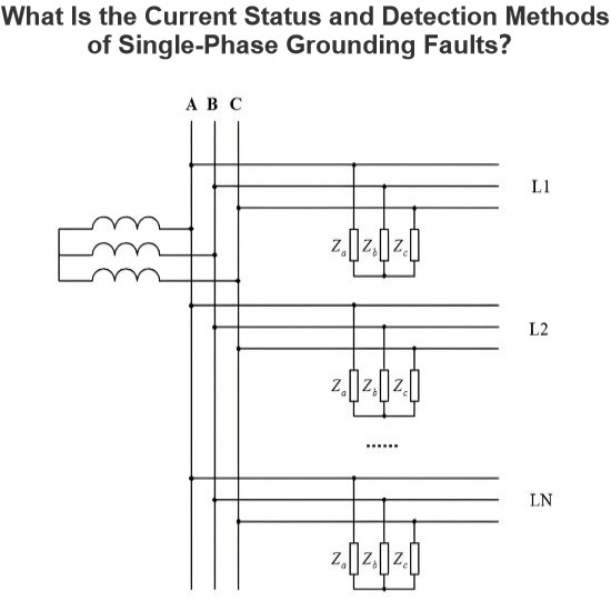
What are the methods for handling single-phase grounding faults in the small-current grounding system of the distribution network?
Current Status of Single-Phase Grounding Fault DetectionThe low accuracy of single-phase grounding fault diagnosis in non-effectively grounded systems is attributed to several factors: the variable structure of distribution networks (such as looped and open-loop configurations), diverse system grounding modes (including ungrounded, arc-suppression coil grounded, and low-resistance grounded systems), the increasing annual ratio of cable-based or hybrid overhead-cable wiring, and complex fault typ
Leon
08/01/2025
Frequency division method for measuring grid-to-ground insulation parameters
The frequency division method enables the measurement of grid-to-ground parameters by injecting a current signal of a different frequency into the open delta side of the potential transformer (PT).This method is applicable to ungrounded systems; however, when measuring the grid-to-ground parameters of a system where the neutral point is grounded via an arc suppression coil, the arc suppression coil must be disconnected from operation beforehand. Its measurement principle is shown in Figure 1.As
Leon
07/25/2025
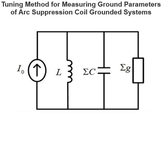
The insulation parameters of the power grid to ground are measured by the tuning method
The tuning method is suitable for measuring the ground parameters of systems where the neutral point is grounded via an arc suppression coil, but not applicable to ungrounded neutral point systems. Its measurement principle involves injecting a current signal with continuously varying frequency from the secondary side of the Potential Transformer (PT), measuring the returned voltage signal, and identifying the system's resonant frequency.During the frequency sweeping process, each injected heter
Leon
07/25/2025
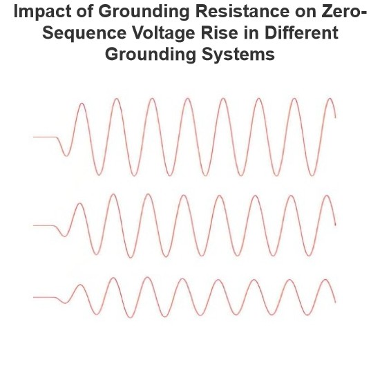
Effect of Transition Resistance at the Grounding Point on the Rising Speed of Zero - sequence Voltage
In an arc - suppression coil grounding system, the rising speed of the zero - sequence voltage is greatly affected by the value of the transition resistance at the grounding point. The larger the transition resistance at the grounding point, the slower the rising speed of the zero - sequence voltage.In an ungrounded system, the transition resistance at the grounding point has basically no impact on the rising speed of the zero - sequence voltage.Simulation Analysis: Arc - suppression Coil Ground
Leon
07/24/2025
Seed Inquiry
Download
Get the IEE Business Application
Use the IEE-Business app to find equipment, obtain solutions, connect with experts, and participate in industry collaboration anytime, anywhere—fully supporting the development of your power projects and business.