Nodal Voltage Analysis Method

Edwiin
06/02/2025

Nodal Voltage Analysis
Nodal voltage analysis is a method for solving electrical networks, particularly useful when all branch currents need to be computed. This approach determines voltages and currents by leveraging the nodes of a circuit.
A node is a terminal where three or more circuit elements connect. Nodal analysis is commonly applied to networks with multiple parallel circuits sharing a common ground terminal, offering the advantage of requiring fewer equations to solve the circuit.
Principles and Application
  • Kirchhoff’s Current Law (KCL): The core principle states that the algebraic sum of all incoming currents at a node must equal the algebraic sum of all outgoing currents.
  • Node Classification:
    • Reference Node: Serves as the ground or zero-potential reference point for all other nodes.
    • Non-Reference Nodes: Nodes with unknown voltages relative to the reference node.
Equation Formulation
The number of independent node equations required is one less than the number of junctions (nodes) in the network. If n represents the number of independent node equations and j is the total number of junctions, the relationship is:n = j - 1
When formulating current expressions, it is assumed that node potentials are always higher than other voltages appearing in the equations.
This method focuses on defining the voltage at each node to find potential differences across elements or branches, making it efficient for analyzing complex circuits with multiple parallel paths.
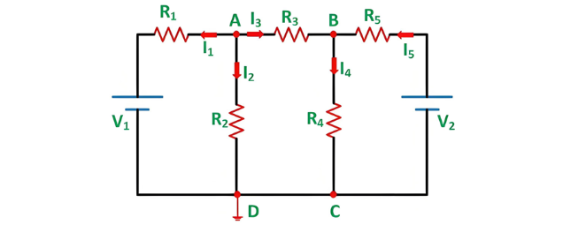
Let's understand the Nodal Voltage Analysis method through the example shown below:
Steps for Solving Networks via Nodal Voltage Analysis
Using the circuit diagram above, the following steps illustrate the analysis process:
Step 1 – Identify Nodes
Identify and label all nodes in the circuit. In the example, nodes are marked as A and B.
Step 2 – Select Reference Node
Choose a reference node (zero potential) where the maximum number of elements connect. Here, node D is selected as the reference node. Let the voltages at nodes A and B be denoted as VA and VB, respectively.
Step 3 – Apply KCL at Nodes
Apply Kirchhoff’s Current Law (KCL) to each non-reference node:
Applying KCL at Node A: (Formulate current expressions based on the circuit configuration, ensuring algebraic sums of incoming/outgoing currents are balanced.)
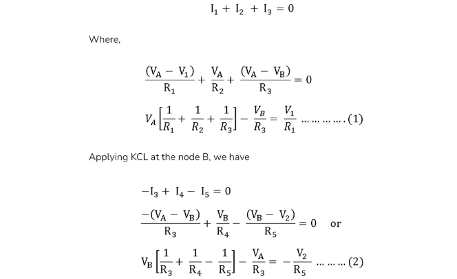
Solving Equation (1) and Equation (2) will yield the values of VA and VB.
Key Advantage of Nodal Voltage Analysis
This method requires writing a minimum number of equations to determine unknown quantities, making it efficient for analyzing complex circuits with multiple nodes.
Edwiin

Load Frequency Control (LFC) & Turbine Governor Control (TGC) in Power System
Brief Introduction to Thermal Generating UnitsElectricity generation relies on both renewable and non - renewable energy resources. Thermal generating units represent a conventional approach to power production. In these units, fuels such as coal, nuclear energy, natural gas, biofuel, and biogas are combusted within a boiler.The boiler of a generating unit is an extremely complex system. In its simplest conception, it can be visualized as a chamber whose walls are lined with pipes, through which
Edwiin
06/06/2025
Why 3-Phase Power? Why Not 6, 12 or More for Power Transmission?
It is well-known that single-phase and three-phase systems are the most prevalent configurations for power transmission, distribution, and end-use applications. While both serve as fundamental power supply frameworks, three-phase systems offer distinct advantages over their single-phase counterparts.Notably, multi-phase systems (such as 6-phase, 12-phase, etc.) find specific applications in power electronics—particularly in rectifier circuits and variable frequency drives (VFDs)—wher
Edwiin
06/05/2025
How Many Poles and Towers are Situated Within a 1-km Span?
The number of distribution poles and transmission towers within a 1-kilometer stretch of overhead lines varies significantly based on multiple factors, including voltage level, power line type, supporting structure, geographical location, local regulations, and specific grid requirements.In urban areas, distribution utility poles are typically positioned at closer intervals, while in rural regions, they are spaced farther apart. Additionally, the use of taller structures for higher-voltage trans
Edwiin
06/05/2025
Synchronizing Power and Torque Coefficient
Definition of Synchronizing PowerSynchronizing power, denoted as Psyn, is defined as the variation in synchronous powerP with respect to changes in the load angle δ. Also referred to as thestiffness of coupling,stability factor, orrigidity factor, it quantifies a synchronous machine’s (generator or motor) inherent tendency to maintain synchronism when connected to infinite busbars.Principle of Synchronism MaintenanceConsider a synchronous generator transmitting a steady power Pa at a
Edwiin
06/04/2025
Inquiry
Download
IEE-Business is dedicated to serving the personnel in the global power industry.
Join IEE-Business, not only can you discover power equipment and power knowledge, but also canhnd like - minded friends!