What is Electrical Drive Systems?

Encyclopedia
04/22/2025

Definition

An electrical drive system is defined as a mechanism designed to regulate the speed, torque, and direction of an electric motor. While each electrical drive system may possess unique characteristics, they also share several common features.

Electrical Drive Systems

The figure below illustrates the typical configuration of a plant - level power distribution network. In this setup, the electrical drive system draws its incoming alternating - current (AC) supply from a Motor Control Center (MCC). The MCC serves as a central hub, overseeing the power distribution to multiple drives situated within a specific area.

In large - scale manufacturing plants, numerous MCCs are often in operation. These MCCs, in turn, receive power from the main distribution center known as the Power Control Centre (PCC). Both the MCC and PCC commonly employ air circuit breakers as the primary power - switching elements. These switching components are engineered to handle electrical loads with ratings of up to 800 volts and 6400 amperes, ensuring reliable and efficient power management within the electrical drive system and the overall plant infrastructure.

image.png

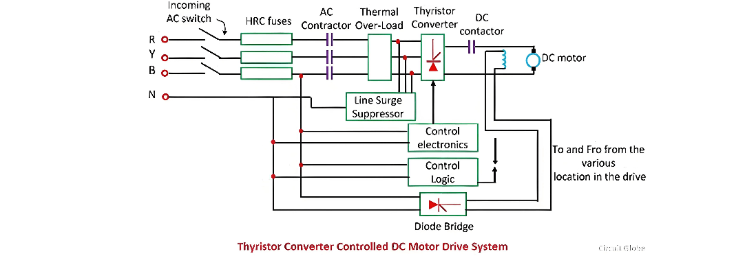
The GTO inverter controlled induction motor drive is shown in the figure below:

image.png

Main Parts of Electrical Drive Systems

The following are the key components of these drive systems:

  • Incoming AC switch

  • Power converter and inverter assembly

  • Outgoing DC and AC switchgear

  • Control logic

  • Motor and the associated load

The main parts of the electrical power system are detailed below.

Incoming AC Switchgear

The incoming AC switchgear comprises a switch - fuse unit and an AC power contactor. These components typically have voltage and current ratings of up to 660V and 800A. Instead of a normal contactor, a bar - mounted contactor is often used, and an air circuit breaker serves as the incoming switch. The use of a bar - mounted contactor extends the rating capabilities up to 1000V and 1200A.

This switchgear is equipped with a High Rupturing Capacity (HRC) fuse rated for up to 660V and 800A. Additionally, it includes a thermal overload protection mechanism to safeguard the system from overloading. In some cases, the contactor of the switchgear can be replaced with a moulded case circuit breaker for enhanced performance and protection.

Power Converter/Inverter Assembly

This assembly is divided into two major sub - blocks: power electronics and control electronics. The power electronics block consists of semiconductor devices, heat sinks, semiconductor fuses, surge suppressors, and cooling fans. These components work together to handle the high - power conversion tasks.

The control electronics block includes a triggering circuit, its own regulated power supply, and a driving and isolation circuit. The driving and isolation circuit is responsible for controlling and regulating the power flow to the motor.

When the drive operates in a closed - loop configuration, it includes a controller along with current and speed feedback loops. The control system features three - port isolation, ensuring that the power supply, inputs, and outputs are isolated with appropriate insulation levels to enhance safety and reliability.

Line Surge Suppressors

Line surge suppressors play a crucial role in protecting the semiconductor converter from voltage spikes. These spikes can occur in the power line due to the switching on and off of loads connected to the same line. The line surge suppressor, in combination with inductance, effectively suppresses these voltage spikes.

When the incoming circuit breaker operates and interrupts the current supply, the line surge suppressor absorbs a certain amount of trapped energy. However, if the power modulator is not a semiconductor device, a line surge suppressor may not be necessary.

Control Logic

Control logic is used for interlocking and sequencing the various operations of the drive system under normal, fault, and emergency conditions. Interlocking is designed to prevent abnormal and unsafe operations, ensuring the system's integrity. Sequencing, on the other hand, ensures that drive operations such as starting, braking, reversing, and jogging are carried out in a pre - determined sequence. For complex interlocking and sequencing tasks, a programmable logic controller (PLC) is often employed to provide flexible and reliable control.

Encyclopedia

The Electricity Encyclopedia is dedicated to accelerating the dissemination and application of electricity knowledge and adding impetus to the development and innovation of the electricity industry.

How to Design and Install a Solar PV System?
Design and Installation of Solar PV SystemsModern society relies on energy for daily needs like industry, heating, transport, and agriculture, mostly met by non-renewable sources (coal, oil, gas). However, these cause environmental harm, are unevenly distributed, and face price volatility due to limited reserves—driving demand for renewable energy.Solar energy, abundant and capable of meeting global needs, stands out. Standalone PV systems (Fig 1) offer energy independence from utilities.
Edwiin
07/17/2025
Load Frequency Control (LFC) & Turbine Governor Control (TGC) in Power System
Brief Introduction to Thermal Generating UnitsElectricity generation relies on both renewable and non - renewable energy resources. Thermal generating units represent a conventional approach to power production. In these units, fuels such as coal, nuclear energy, natural gas, biofuel, and biogas are combusted within a boiler.The boiler of a generating unit is an extremely complex system. In its simplest conception, it can be visualized as a chamber whose walls are lined with pipes, through which
Edwiin
06/06/2025
Why 3-Phase Power? Why Not 6, 12 or More for Power Transmission?
It is well-known that single-phase and three-phase systems are the most prevalent configurations for power transmission, distribution, and end-use applications. While both serve as fundamental power supply frameworks, three-phase systems offer distinct advantages over their single-phase counterparts.Notably, multi-phase systems (such as 6-phase, 12-phase, etc.) find specific applications in power electronics—particularly in rectifier circuits and variable frequency drives (VFDs)—wher
Edwiin
06/05/2025
How Many Poles and Towers are Situated Within a 1-km Span?
The number of distribution poles and transmission towers within a 1-kilometer stretch of overhead lines varies significantly based on multiple factors, including voltage level, power line type, supporting structure, geographical location, local regulations, and specific grid requirements.In urban areas, distribution utility poles are typically positioned at closer intervals, while in rural regions, they are spaced farther apart. Additionally, the use of taller structures for higher-voltage trans
Edwiin
06/05/2025
Inquiry
Download
IEE-Business is dedicated to serving the personnel in the global power industry.
Join IEE-Business, not only can you discover power equipment and power knowledge, but also canhnd like - minded friends!