Design and Installation of Solar PV Systems
Modern society relies on energy for daily needs like industry, heating, transport, and agriculture, mostly met by non-renewable sources (coal, oil, gas). However, these cause environmental harm, are unevenly
distributed, and face price volatility due to limited reserves—driving demand for renewable energy.
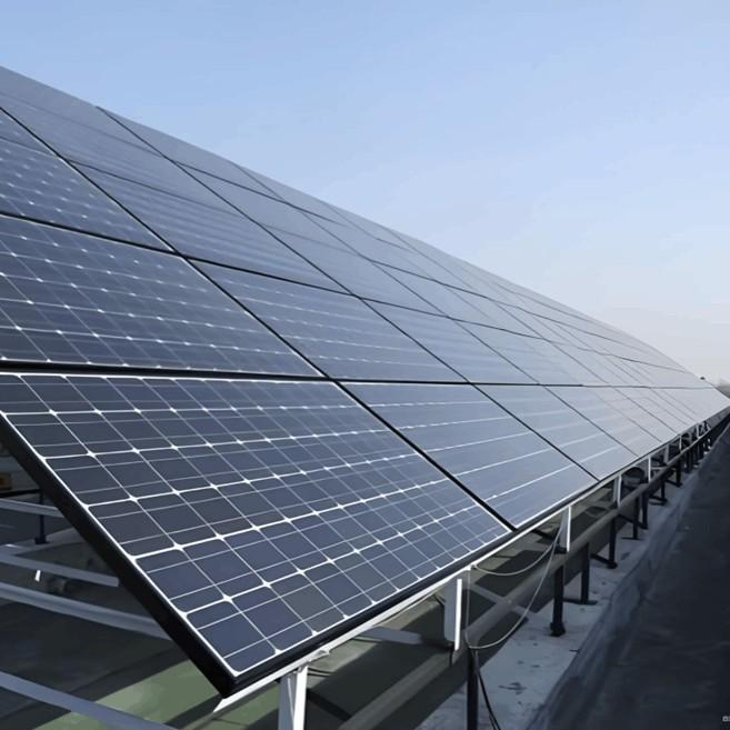
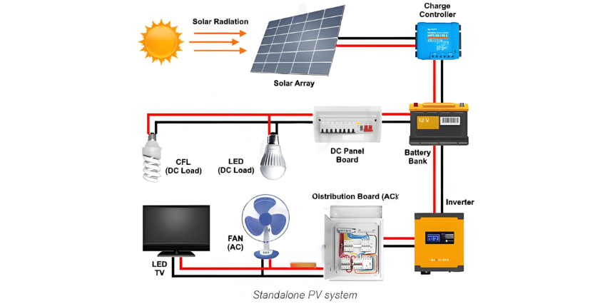
Solar energy, abundant and capable of meeting global needs, stands out. Standalone PV systems (Fig 1) offer energy independence from utilities. Below is an overview of their planning, design, and installation for electricity generation.
Planning of a Standalone PV System
Site Assessment & Survey:
Shade Minimization: Ensure the installation site (rooftop or ground) is free from shading structures, and no future constructions will block solar radiation.
Surface Area: Determine the site area to estimate the number/size of PV panels, and plan placement for inverters, converters, and battery banks.
Rooftop Considerations: For tilted roofs, note the tilt angle and use appropriate mounting to maximize solar incidence (ideally perpendicular to panels).
Cable Routing: Plan routes for cables (connecting inverter, battery bank, charge controller, and PV array) to minimize cable usage and voltage drop, balancing efficiency and cost.
Solar Energy Resource Assessment:
Insolation Data: Measure or obtain (from meteorological stations) solar energy received, using either kilowatt-hours per square meter per day (kWh/m²/day) or daily Peak Sun Hours (PSH, hours with average irradiance of 1000 W/m²).
Key Metric: Use PSH for simplified calculations (distinguish from "mean sunshine hours," which reflects duration rather than energy). Adopt the lowest monthly mean insolation to ensure system reliability during low-sun periods.
Considerations for Standalone PV Systems
1. Energy Demand Calculation
The system size depends on load demand, calculated as:
Daily energy demand (Wh) = Sum of (appliance power rating in watts × daily operating hours).
Use the highest daily demand to balance reliability and cost (ensures operation during peak usage, though this increases system cost).
2. Inverter & Charge Controller Sizing
Inverter: Rated 25% higher than total load (to account for losses).
Example: For a 2400W load, a 3000W inverter (2400W × 1.25) is needed.
Charge Controller: Current rating = 125% of PV panel short-circuit current (safety factor).
Example: 4 panels with 10A short-circuit current require a 50A controller (4×10A ×1.25).
Note: MPPT controllers follow manufacturer specifications.
3. Daily Energy to Inverter
Account for inverter efficiency (e.g., 90%):
4. System Voltage
Determined by battery voltage (typically 12V, 24V, etc.), with higher voltages reducing cable loss. Example: 24V system.
5. Battery Sizing
Key parameters: depth of discharge (DOD), autonomy days, and system voltage.
Usable capacity = Battery Ah × DOD.
Required charge capacity = Energy from battery / system voltage.
Example: 3000Wh from battery in a 24V system → 125Ah required.
For 12V, 100Ah batteries (70% DOD):
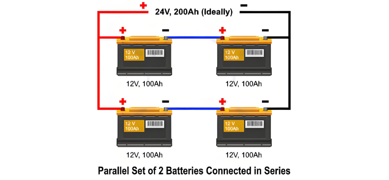
So, in total there will be four batteries of 12 V, 100 Ah. Two connected in series and two connected in parallel.Also, the required capacity of batteries can be found by the following formula.

Sizing of the PV Array
Total PV array capacity (W): Calculated using the lowest daily peak sun hours (or Panel Generation Factor, PFG) and daily energy demand:
Total Wₚₑₐₖ = (Daily energy demand (Wh) / PFG) × 1.25 (scaling factor for losses).
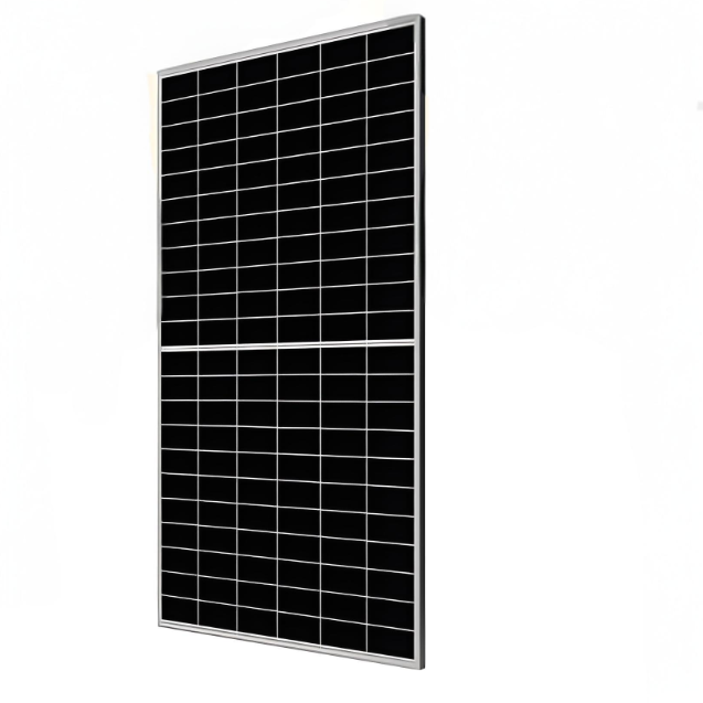
Number of modules: Divide total Wₚₑₐₖ by the rated power of a single panel (e.g., 160W).
Example: For a 3000Wh daily demand and PFG = 3.2, total Wₚₑₐₖ = 3000 / 3.2 ≈ 931W. With 160W panels, 6 modules are needed (931 / 160 ≈ 5.8, rounded up).
Loss factors (to adjust PFG): Include sunlight angle (5%), non-max power point (10%, excluded for MPPT), dirt (5%), aging (10%), and high temperature (>25°C, 15%).
Sizing of the Cables
Key considerations: Current capacity, minimal voltage drop (<2%), resistive losses, weather resistance (water/UV proof).
Cross-sectional area formula:
A = (ρ × Iₘ × L / VD) × 2
(ρ = resistivity, Iₘ = max current, L = cable length, VD = permissible voltage drop).
Balance: Avoid undersizing (energy loss/accidents) or oversizing (cost inefficiency). Use appropriate circuit breakers and connectors.