• Product
  • Suppliers
  • Manufacturers
  • Solutions
  • Free tools
  • Knowledges
  • Experts
  • Communities
Search


Voltage in Series Circuits

Electrical4u
Field: Basic Electrical
0
China

What are Voltages in Series?

A series circuit or series connection refers to when two or more electrical components are linked together in a chain-like an arrangement within a circuit. In this kind of circuit, there is only a single way for charge to pass through the circuit. The potential variation in charge across two points in an electrical circuit is known as voltage. In this article, we will discuss in detail voltages in a series circuit.

The battery of a circuit provides energy for the charge to pass through the battery and to create a potential difference among the ends of the external circuit. Now, if we assume a cell of 2 volts, it will create a potential difference of 2 volts across the external circuit.

The electric potential value at the positive terminal is 2 volts greater than the negative terminal. So, when charge flows from the positive to the negative terminal, it causes a loss of 2 volts in electrical potential.

This is termed as voltage drop. This happens when the electrical energy of the charge is converted into some other forms (mechanical, heat, light etc) while passing through the components (resistors or load) in the circuit.

voltage in series
If we consider a circuit with more than one resistor connected in series and are powered with a 2V cell, the total loss of electrical potential is 2V. That is, there will be a certain voltage drop in each connected resistor. But we can see that the sum of the voltage drop of all the components will be 2V which is equivalent to the voltage rating of the power source.

Mathematically, we can express it as

By using Ohm’s law the individual voltage drops can be calculated as

Now, we can assume a series circuit comprises of 3 resistors and powered by a 9V energy source. Here, we are going to find out the potential difference at a different location during the passage of current throughout the series circuit.

The locations are marked in red color in the circuit below. We know that current passes in the direction from the positive terminal towards the negative terminal of the source. The negative sign of the voltage or potential difference represents the loss in potential due to the resistor.

The electrical potential difference of different points in the circuit can be represented with the help of a diagram called the electric potential diagram that is shown below.
electric potential voltage in series
In this example, the electrical potential at A = 9V since it is the higher potential terminal. The electrical potential at H = 0V since it is the negative terminal. When the current passes through the 9V power source, the charge gains 9V of electrical potential, which is from H to A. While the current passes throughout the external circuit, the charge loses this 9V completely.

Here, this happens in three steps. There will be drop-in voltage when the current passes through the resistors but no voltage drop occurs when the passage is through the mere wire. So, we can see that between the points AB, CD, EF and GH; there is no voltage drop. But between points B and C, the voltage drop is 2V.

That is the source voltage 9V becomes 7V. Next, between the points D and E, the voltage drop is 4V. At this point, the voltage 7V becomes 3V. At last, between the points F and G, the voltage drop is 3V. At this point, the voltage 3V becomes 0V.

The portion of the circuit between the points G and H, there is no energy for the charge. So, it desires an energy boost for the passage through the external circuit again. This is provided by the power source as the charge passes from H to A.

The several voltage sources in series can be replaced by a single voltage source by taking the sum total of all the voltage sources. But we have to consider the polarity as shown below.
voltage in series

AC Voltage Sources in Series

In the case of AC voltage sources in series, the voltage sources can be added or combined together to form a single source provided that the angular frequency (ω) of the connected sources are identical. If the AC voltage sources connected in series are of different angular frequencies, it can be added together provided the current through the connected sources is the same.
ac voltage sources in series

Application of Voltage in Series Circuits

The application of voltages in series circuits include:

  • Voltage divider.

  • Fire alarm battery.

  • Batteries in remote, toys etc.

  • Lighting purposes in a train, Christmas tree etc.

Source: Electrical4u.

Statement: Respect the original, good articles worth sharing, if there is infringement please contact delete.

Give a tip and encourage the author!
Recommended
Difference Between Electromagnet and Permanent Magnet
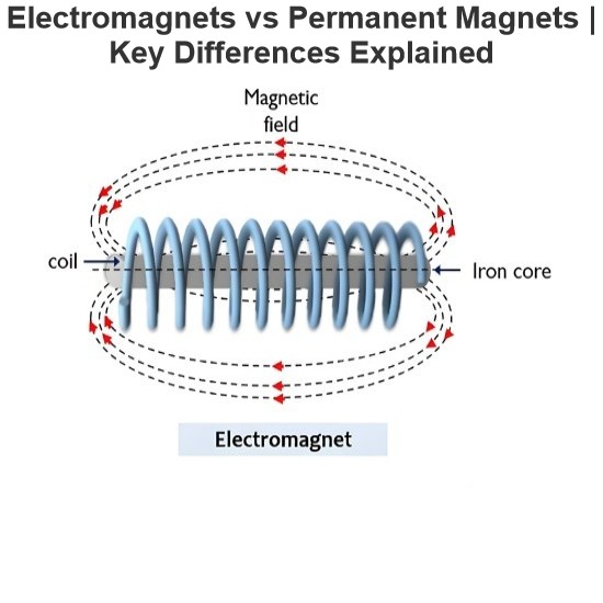
Electromagnets vs. Permanent Magnets: Understanding the Key DifferencesElectromagnets and permanent magnets are the two primary types of materials that exhibit magnetic properties. While both generate magnetic fields, they differ fundamentally in how these fields are produced.An electromagnet generates a magnetic field only when an electric current flows through it. In contrast, a permanent magnet inherently produces its own persistent magnetic field once it has been magnetized, without requirin
Edwiin
08/26/2025
Working Voltage in Power System
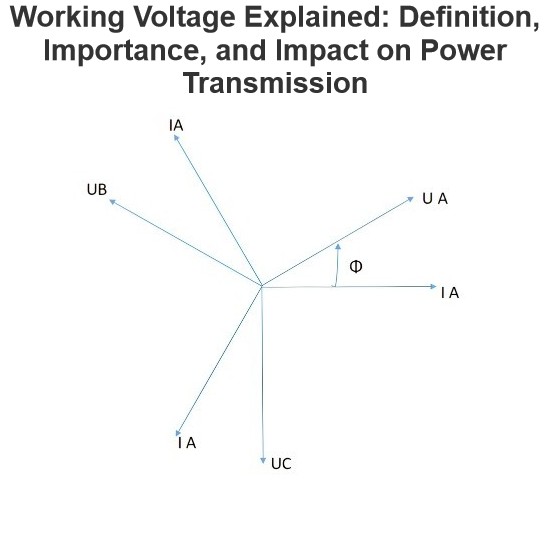
Working VoltageThe term "working voltage" refers to the maximum voltage that a device can withstand without sustaining damage or burning out, while ensuring the reliability, safety, and proper operation of both the device and associated circuits.For long-distance power transmission, the use of high voltage is advantageous. In AC systems, maintaining a load power factor as close to unity as possible is also economically necessary. Practically, heavy currents are more challenging to handle than hi
Encyclopedia
07/26/2025
What is a Pure Resistive AC Circuit?
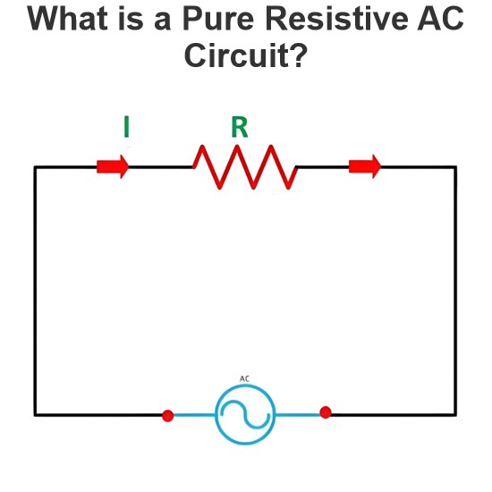
Pure Resistive AC CircuitA circuit containing only a pure resistanceR(in ohms) in an AC system is defined as a Pure Resistive AC Circuit, devoid of inductance and capacitance. Alternating current and voltage in such a circuit oscillate bidirectionally, generating a sine wave (sinusoidal waveform). In this configuration, power is dissipated by the resistor, with voltage and current in perfect phase—both reaching their peak values simultaneously. As a passive component, the resistor neither
Edwiin
06/02/2025
What is a Pure Capacitor Circuit?
Pure Capacitor CircuitA circuit comprising only a pure capacitor with capacitanceC(measured in farads) is termed a Pure Capacitor Circuit. Capacitors store electrical energy within an electric field, a characteristic known ascapacitance(alternatively referred to as a "condenser"). Structurally, a capacitor consists of two conductive plates separated by a dielectric medium—common dielectric materials include glass, paper, mica, and oxide layers. In an ideal AC capacitor circuit, the current
Edwiin
06/02/2025
Seed Inquiry
Download
Get the IEE Business Application
Use the IEE-Business app to find equipment, obtain solutions, connect with experts, and participate in industry collaboration anytime, anywhere—fully supporting the development of your power projects and business.