Resistance in Series Explained

The Electricity Forum
03/16/2024

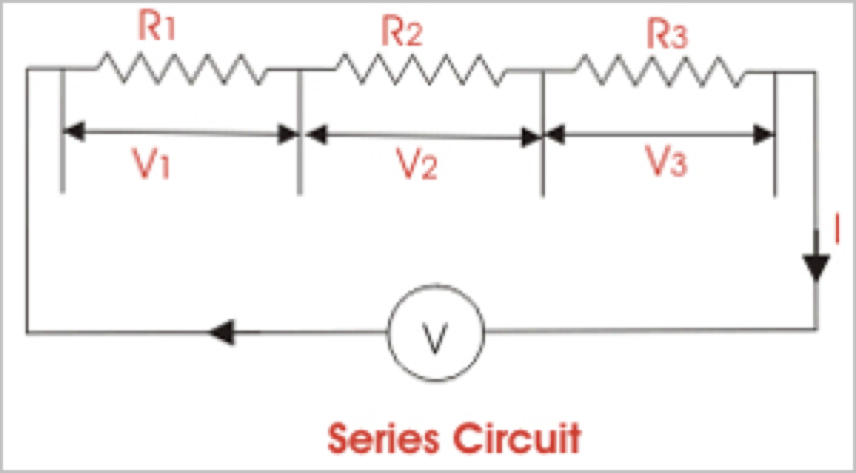
Resistance in series refers to the arrangement of individual resistors end to end in a circuit so that the current flows through each resistor. In this configuration, the total resistance (R) of the circuit is equal to the sum of the individual resistances, also known as the equivalent R.

WechatIMG1533.png

To calculate the total R in a series circuit, the individual resistances of each resistor are added together. The formula to calculate the equivalent resistance in a series connection is Rtotal = R1 + R2 + R3 + ..., where R1, R2, R3, etc., represent the individual resistances of each resistor in the circuit.

Ohm's law also applies to series circuits, where the current through each resistor is the same, but the voltage across each resistor is proportional to its R. The total voltage across the series combination of resistors equals the sum of the voltage drops across each resistor.

It is important to note that the total R in a series circuit is always greater than the resistance of any individual resistor in the circuit due to the cumulative effect of each resistor's R.

On the other hand, resistors connected in parallel result in a parallel circuit. The equivalent R of a parallel circuit is calculated differently from a series connection. Instead of adding the individual resistances, the reciprocal of each R is added, and the resulting value is inverted to obtain the equivalent resistance.


R in Series - Parallel

When you place R-I-S, their ohmic values add up arithmetically to reach the total (or net) R.

We can connect a series of resistors (equal to the sum of the individual resistances of a parallel circuit), all having identical ohmic values, in parallel sets of series networks or series sets of parallel networks. When we do either of these things, we get a series-parallel network that can greatly increase the total power handling capacity of the network over the power-handling capacity of a single parallel resistor.

WechatIMG1534.png
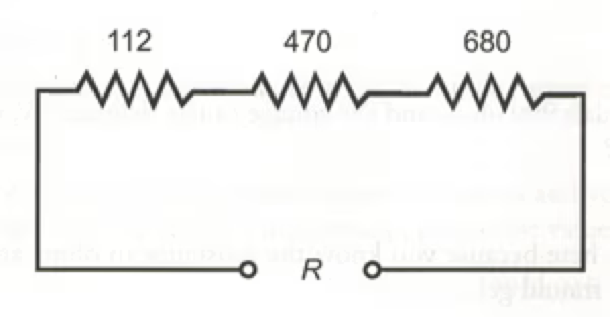
Fig. 4-14. Three resistors in series. 

Sometimes, the total single equivalent R of the combination circuit in a series parallel network equals the value of any one of the resistors. This always happens if the parallel branches or parallel combinations of the connection components are all identical and are arranged in a network called an n-by-n (or n x n) matrix. That means when n is a whole number, we have n series sets of n resistors connected in parallel, or else we have n parallel sets of n resistors connected in series in the circuit. These two arrangements yield the same practical result for electrical circuits.

A combination of series parallel combinations array of n by n resistors, all having identical ohmic values and identical power ratings, will have n2 times the power-handling capability of any resistor by itself. For example, a 3 x 3 series-parallel matrix of 2 W resistors can handle up to 32 x 2 = 9 x 2 = 18 W. If we have a 10 x 10 array of 1/2 W resistors, then it can dissipate up to 102 x 1/2 = 50 W. We multiply the power-handling capacity of each individual resistor by the total number of resistors in the matrix.

The above-described scheme works if, but only if, all of the resistors have identical ohmic values according to ohms law and identical power-dissipation ratings in terms of total voltage drops when the sum of the voltage drops across each resistor. If the resistors have values that differ even a little bit from one another, one of the components will likely draw more current than it can withstand so that it will burn out, no matter the voltage source. Then the current distribution in the network will change further, increasing the likelihood that a second resistor will fail, and maybe more.

If you need a resistor that can handle 50 W and a certain series-parallel connection of the network will handle 75 W, that's fine. But you should not "push your luck" and expect to get away with using a network that will handle only 48 W in the same application. You should allow some extra tolerance, say 10 per cent over the minimum rating. If you expect the network to dissipate 50W, you should build it to handle 55 W or a bit more. You don't have to use "overkill," however. You'll waste resources if you cobble together a network that can handle 500W when you only expect it to cope with 50W—unless that's the only convenient combination you can make with available resistors.

Statement: Respect the original, good articles worth sharing, if there is infringement please contact delete.

The Electricity Forum

Electricity Forum publishes Electricity Today T&D Magazine and Intelligent Power Today Industrial Electrical Magazine. We publish electrical technical handbooks and associated digital magazine advertising supplements.

What is a Pure Resistive AC Circuit?
Pure Resistive AC CircuitA circuit containing only a pure resistanceR(in ohms) in an AC system is defined as a Pure Resistive AC Circuit, devoid of inductance and capacitance. Alternating current and voltage in such a circuit oscillate bidirectionally, generating a sine wave (sinusoidal waveform). In this configuration, power is dissipated by the resistor, with voltage and current in perfect phase—both reaching their peak values simultaneously. As a passive component, the resistor neither
Edwiin
06/02/2025
What is a Pure Capacitor Circuit?
Pure Capacitor CircuitA circuit comprising only a pure capacitor with capacitanceC(measured in farads) is termed a Pure Capacitor Circuit. Capacitors store electrical energy within an electric field, a characteristic known ascapacitance(alternatively referred to as a "condenser"). Structurally, a capacitor consists of two conductive plates separated by a dielectric medium—common dielectric materials include glass, paper, mica, and oxide layers. In an ideal AC capacitor circuit, the current
Edwiin
06/02/2025
Resistance Switching in a Circuit Breaker
Resistance SwitchingResistance switching refers to the practice of connecting a fixed resistor in parallel with the contact gap or arc of a circuit breaker. This technique is applied in circuit breakers with high post-arc resistance in the contact space, primarily to mitigate re-striking voltages and transient voltage surges.Severe voltage fluctuations in power systems arise from two main scenarios: interrupting low-magnitude inductive currents and breaking capacitive currents. Such overvoltages
Edwiin
05/23/2025
What is Biot Savart Law?
The Biot-Savart Law is employed to determine the magnetic field intensity dHnear a current-carrying conductor. In other words, it describes the relationship between the magnetic field intensity generated by a source current element. This law was formulated in 1820 by Jean-Baptiste Biot and Félix Savart. For a straight wire, the direction of the magnetic field adheres to the right-hand rule. The Biot-Savart Law is also referred to as Laplace’s law or Ampère’s law.Conside
Edwiin
05/20/2025
Inquiry
Download
IEE-Business is dedicated to serving the personnel in the global power industry.
Join IEE-Business, not only can you discover power equipment and power knowledge, but also canhnd like - minded friends!