What is Power in AC Circuit?

Electrical4u
03/09/2024

AC circuits are usually three-phase for electrical distribution and electrical transmission purposes. Single phase circuits are commonly used in our domestic supply system.

The total power of a three-phase AC circuit is equal to three times the single phase power.

So if the power in a single phase of a three-phase system is ‘P’, then the total power of the three-phase system would by 3P (provided the three-phase system is perfectly balanced).

But if the three-phase system is not exactly balanced, then the total power of the system would be the sum of the power of individual phases.

Suppose, in a three phase system, the power at R phase is PR , at Y phase is PY and at B phase is PB, then total power of the system would be

This is simple scalar sum, since power is a scalar quantity. This is the season, if we consider only single phase during calculating and analyzing of three phase power, it is enough.

Let us consider, network A is electrically connected with network B as shown in the figure below:

electrically connected network

Let us consider the expression of the voltage waveform of a single phase system is:
Where V is the amplitude of the waveform, ω is the angular velocity of propagation of the wave.

Now, consider the current of the system is i(t) and this current has a phase difference from the voltage by an angle φ. That means current wave propagates with φ radiant lag in respect of the voltage. The voltage and current waveform can be represented graphically as shown below:

voltage waveform

The current waveform in this case can be represented as:

current voltage waveform

Now, the expression of the instantaneous power,

[where Vrms and Irms is the root mean square value of voltage and current waveform]

Now, let us plot the term P versus time,

p versus time

It is seen from the graph that, the term P does not have any negative value. So, it will have a nonzero average value. It is sinusoidal with a frequency twice of system frequency. Let us now plot second term of the power equation, i.e. Q.

second term of power equation

This is purely sinusoidal and has a zero average value. So from of these two graphs, it is clear that P is the component of power in an AC circuit, which actually transported from network A to network B. This power is consumed in network B as electric power.

Q on the other hand does not really flow from network A to network B. Rather it oscillate between network A and B. This is also component of power, actually flowing into and out of the inductor, capacitor like energy storage elements of the network.

Here, P is known as the real or active part of the power and Q is known as imaginary or reactive part of the power.

Hence, P is called real power or active power, and Q is called imaginary or active power. The unit of active power is Watt, whereas the unit of reactive power is Voltage Ampere Reactive or VAR.

We have already considered,

where, S is the product of root mean value of voltage and current i.e.

This product of RMS value of voltage and current of a system is referred as apparent power is Voltage Ampere or VA. So,

This can be represented in complex form as

Again, the expression of the real power is

where ɸ is the angle between voltage and current phasor. So,

So, here in the expression P, cos ɸ is the factor which determines the real power component of an apparent power S.

This is why the term cos ɸ in the expression of real power is called power factor. For both positive and negative value of ɸ, cos ɸ is always positive.

This implies, regardless of the sign of ɸ (which is dependent on whether the current is lagging or leading the voltage) real power is always positive.

That means it flows from the sending end (Network A) to receiving end (Network B). We have also shown the same earlier when looking at the waveform for real power.

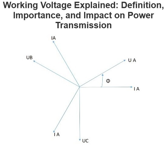
Now if the current is leading the voltage, then the angle between voltage and current phasor is negative, taking the voltage phasor as reference:

Voltage phasor

In that case the reactive component of the power is negative,

Power Triangle

The relation between apparent power to active power and reactive power can be represented in trigonometric form as shown below.

power triangle

Now, if current is lagging the voltage the angle between voltage and current phasor is positive, taking the voltage phasor as reference.

In this case, the reactive component of power is positive. Since,

The power triangle is represented as shown below.

the power triangle

If the impedance of the network is capacitive, the current leads the voltage, and in case of inductive network the current lags voltage. So we can conclude, the reactive power is negative in the case of capacitive reactance and it is positive and in the case of inductive reactance.

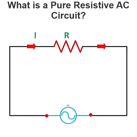
If the network is purely resistive, there would not be any angular difference between current and voltage. Hence,

So the reactive power in this case would be,

Thus, there is no reactive power generated or consumed in the network.

Source: Electrical4u

Statement: Respect the original, good articles worth sharing, if there is infringement please contact delete.


Electrical4u

Electrical4U is dedicated to the teaching and sharing of all things related to electrical and electronics engineering.

What is a Pure Resistive AC Circuit?
Pure Resistive AC CircuitA circuit containing only a pure resistanceR(in ohms) in an AC system is defined as a Pure Resistive AC Circuit, devoid of inductance and capacitance. Alternating current and voltage in such a circuit oscillate bidirectionally, generating a sine wave (sinusoidal waveform). In this configuration, power is dissipated by the resistor, with voltage and current in perfect phase—both reaching their peak values simultaneously. As a passive component, the resistor neither
Edwiin
06/02/2025
What is a Pure Capacitor Circuit?
Pure Capacitor CircuitA circuit comprising only a pure capacitor with capacitanceC(measured in farads) is termed a Pure Capacitor Circuit. Capacitors store electrical energy within an electric field, a characteristic known ascapacitance(alternatively referred to as a "condenser"). Structurally, a capacitor consists of two conductive plates separated by a dielectric medium—common dielectric materials include glass, paper, mica, and oxide layers. In an ideal AC capacitor circuit, the current
Edwiin
06/02/2025
Resistance Switching in a Circuit Breaker
Resistance SwitchingResistance switching refers to the practice of connecting a fixed resistor in parallel with the contact gap or arc of a circuit breaker. This technique is applied in circuit breakers with high post-arc resistance in the contact space, primarily to mitigate re-striking voltages and transient voltage surges.Severe voltage fluctuations in power systems arise from two main scenarios: interrupting low-magnitude inductive currents and breaking capacitive currents. Such overvoltages
Edwiin
05/23/2025
What is Biot Savart Law?
The Biot-Savart Law is employed to determine the magnetic field intensity dHnear a current-carrying conductor. In other words, it describes the relationship between the magnetic field intensity generated by a source current element. This law was formulated in 1820 by Jean-Baptiste Biot and Félix Savart. For a straight wire, the direction of the magnetic field adheres to the right-hand rule. The Biot-Savart Law is also referred to as Laplace’s law or Ampère’s law.Conside
Edwiin
05/20/2025
Inquiry
Download
IEE-Business is dedicated to serving the personnel in the global power industry.
Join IEE-Business, not only can you discover power equipment and power knowledge, but also canhnd like - minded friends!