Unit of Electrical Resistance - Understanding the Ohm

The Electricity Forum
03/16/2024

The unit of electrical resistance, the Ohm, is a cornerstone of the electrical world. Its importance in governing the behaviour of electric currents, designing efficient circuits, and ensuring the safe operation of devices cannot be overstated. By understanding the intricacies of resistance and Ohm's law, it is possible to harness the power of electricity to create innovative and practical solutions that benefit our daily lives.

WechatIMG1538.png

The world of electricity is complex and fascinating, with numerous components working in unison to power our lives. One such essential element is the unit of electrical resistance, the Ohm (ω), named after Georg Simon Ohm, a German physicist. The Ohm plays a vital role in the functioning of electrical circuits and everyday devices. This article delves into the intricacies of this unit and its significance in the realm of electricity.

First and foremost, it is crucial to understand the basic concept of resistance. In simple terms, resistance is the opposition to the flow of electric current through a conductor. It is an essential factor that influences the behaviour and efficiency of electrical circuits. The Ohm (Ω) is the SI unit of electric resistance, represented by the Greek letter omega (ω). One Ohm is defined as the resistance of a conductor that allows one ampere of current to flow when one volt of potential difference is applied across it.

Ohm's law defines the relationship between resistance, voltage, and electric current, a fundamental principle in electrical engineering. The law states that the current passing through a conductor is directly proportional to the voltage applied and inversely proportional to its resistance. Mathematically, it is expressed as V = IR, where V is the voltage, I is the electric current, and R is the resistance. This equation helps in determining the resistance in various circuits and devices.

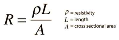
Several factors influence the resistance of a material, including its resistivity, length, cross-sectional area, and temperature. For example, materials with high resistivity, like insulators, have greater resistance than conductors, which have low resistivity. Additionally, longer conductors and those with smaller cross-sectional areas have higher resistance compared to shorter conductors and those with larger cross-sectional areas. The temperature of a material also affects its resistance, as the resistance typically increases with a temperature rise.


How do I measure a electrical resistance?

You can use a multimeter, a versatile electronic measuring instrument, to measure the resistance of a component or a circuit. A multimeter can measure various electrical parameters such as voltage, current, and resistance. Follow these steps to measure the resistance of a component or circuit:

  1. Turn off the power: Ensure that the component or circuit is disconnected from any power source before measuring resistance. Measuring resistance with power applied can damage the multimeter and the component or circuit being tested.

  2. Choose the right setting: Set the multimeter to the resistance mode, often indicated by the symbol Ω (Ohm) on the dial or mode selection button. Some multimeters have an auto-ranging feature, automatically selecting the appropriate range based on the measured resistance. If your multimeter has manual ranging, choose the range closest to, but higher than, the expected resistance.

  3. Prepare the component or circuit: If you are measuring the resistance of a single component like a resistor, remove it from the circuit to avoid inaccurate readings due to parallel or series resistances. Also, disconnect the part from other components that may affect the measurement for in-circuit measurements.

  4. Connect the probes: Touch the multimeter's red probe to one end of the component or circuit and the black probe to the other end. Ensure that the examinations make proper contact with the component or circuit terminals to obtain accurate readings.

  5. Read the resistance: The multimeter display will show the measured resistance in ohms (Ω). If the multimeter has auto-ranging, the display will also indicate the appropriate unit, such as kilohms (kΩ) or megaohms (MΩ). If the resistance value fluctuates, maintain stable contact between the probes and the component or circuit terminals.

  6. Interpret the results: Compare the measured resistance with the expected or specified value for the component or circuit. If there is a significant deviation, the component might be damaged, or the circuit may have a fault.

Factors like temperature and contact resistance between the probes and the component can influence the readings when measuring resistance. Therefore, it's essential to consider these factors when interpreting the measurement results.

Resistance

Resistance plays a critical role in electrical circuits, as it regulates the flow of current and maintains the proper functioning of devices. Limiting the current flow ensures that electrical components do not become overheated or overloaded. Resistors are passive electronic components specifically designed to provide a precise amount of resistance in a circuit.

Impedance, another essential concept in electricity, is closely related to resistance. While resistance refers to the opposition of a direct current (DC), impedance encompasses both resistance and reactance, the latter being the opposition to alternating current (AC) due to capacitance or inductance. Essentially, impedance is the total opposition to the flow of alternating current, combining both resistance and reactance.

The applications are vast and varied, encompassing everyday life and advanced technology. For example, resistance is integral to household appliances like electric heaters, toasters, and incandescent light bulbs, which help generate heat or light. It also plays a significant role in the design of electronic circuits and complex systems like computer processors.


The Electricity Forum

Electricity Forum publishes Electricity Today T&D Magazine and Intelligent Power Today Industrial Electrical Magazine. We publish electrical technical handbooks and associated digital magazine advertising supplements.

What is a Pure Resistive AC Circuit?
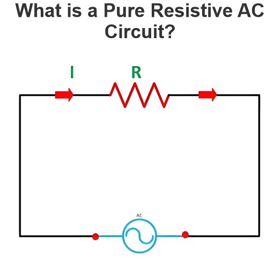
Pure Resistive AC CircuitA circuit containing only a pure resistanceR(in ohms) in an AC system is defined as a Pure Resistive AC Circuit, devoid of inductance and capacitance. Alternating current and voltage in such a circuit oscillate bidirectionally, generating a sine wave (sinusoidal waveform). In this configuration, power is dissipated by the resistor, with voltage and current in perfect phase—both reaching their peak values simultaneously. As a passive component, the resistor neither
Edwiin
06/02/2025
What is a Pure Capacitor Circuit?
Pure Capacitor CircuitA circuit comprising only a pure capacitor with capacitanceC(measured in farads) is termed a Pure Capacitor Circuit. Capacitors store electrical energy within an electric field, a characteristic known ascapacitance(alternatively referred to as a "condenser"). Structurally, a capacitor consists of two conductive plates separated by a dielectric medium—common dielectric materials include glass, paper, mica, and oxide layers. In an ideal AC capacitor circuit, the current
Edwiin
06/02/2025
Resistance Switching in a Circuit Breaker
Resistance SwitchingResistance switching refers to the practice of connecting a fixed resistor in parallel with the contact gap or arc of a circuit breaker. This technique is applied in circuit breakers with high post-arc resistance in the contact space, primarily to mitigate re-striking voltages and transient voltage surges.Severe voltage fluctuations in power systems arise from two main scenarios: interrupting low-magnitude inductive currents and breaking capacitive currents. Such overvoltages
Edwiin
05/23/2025
What is Biot Savart Law?
The Biot-Savart Law is employed to determine the magnetic field intensity dHnear a current-carrying conductor. In other words, it describes the relationship between the magnetic field intensity generated by a source current element. This law was formulated in 1820 by Jean-Baptiste Biot and Félix Savart. For a straight wire, the direction of the magnetic field adheres to the right-hand rule. The Biot-Savart Law is also referred to as Laplace’s law or Ampère’s law.Conside
Edwiin
05/20/2025
Inquiry
Download
IEE-Business is dedicated to serving the personnel in the global power industry.
Join IEE-Business, not only can you discover power equipment and power knowledge, but also canhnd like - minded friends!