Magnetic Reluctance: What is it?

Electrical4u
03/09/2024

What is Reluctance?

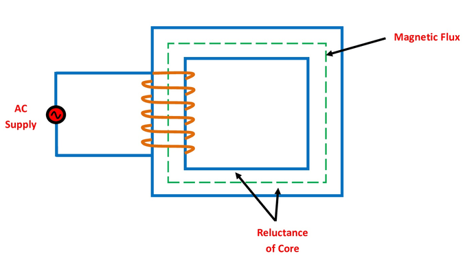
Magnetic reluctance (also known as reluctance, magnetic resistance, or a magnetic insulator) is defined as the opposition offered by a magnetic circuit to the production of magnetic flux. It is the property of the material that opposes the creation of magnetic flux in a magnetic circuit.

Reluctance of Transformer Core.png
Reluctance of Transformer Core

In an electrical circuit, the resistance opposes the flow of current in the circuit and it dissipates the electric energy. The magnetic reluctance in a magnetic circuit is analogous to the resistance in an electric circuit as it opposes the production of magnetic flux in a magnetic circuit but it does not give rise to the dissipation of energy rather it stores magnetic energy.

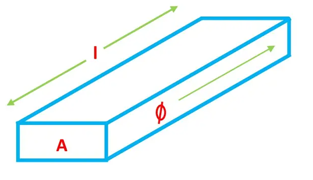
Reluctance is directly proportional to the length of the magnetic circuit and inversely proportional to the area of the cross-section of the magnetic path. It is a scalar quantity and denoted by S. Note that a scalar quantity is one which is fully described by a magnitude (or numerical value) only. No direction is required to define the scalar quantity.

Reluctance of Magnetic Bar.png
Reluctance of Magnetic Bar

Mathematically it can be expressed as

  \begin{align*} S = \frac {l}{\mu_0 \mu_r A} \end{align*}

where, l = length of the magnetic path in meters

\mu_0 = permeability of free space (vacuum) = 4 \pi * 10^-^7 Henry/meter

\mu_r = relative permeability of a magnetic material

A = Cross sectional area in square meters (m^2)

In AC as well as DC magnetic fields, the reluctance is the ratio of the magnetomotive force (m.m.f) to the magnetic flux in a magnetic circuit. In a pulsating AC or DC field, the reluctance is also pulsating.

Thus it can be expressed as

  \begin{align*} Relectance (S) = \frac {m.m.f}{flux} =  \frac {F}{\phi} \end{align*}

Reluctance in a Series Magnetic Circuit

Like in a series electrical circuit, the total resistance is equal to the sum of the individual resistances,

  \begin{align*} R = R_1 + R_2 + R_3 +.............+R_n \end{align*}

Where, R = \frac {\rho l}{A}   (\rho = Resistivity)

Similarly, in a series of magnetic circuits, the total reluctance equals the sum of the individual reluctances encountered around the closed flux path.

  \begin{align*} S = S_1 + S_2 + S_3 +.............+S_n \end{align*}

Where, S = \frac {l}{\mu_0 \mu_r A}

What is Permeability?

The permeability or magnetic permeability is defined as the ability of a material to allow the magnetic lines of force to pass through it. It helps the development of the magnetic field in a magnetic circuit.  

The SI unit of permeability is Henry/meter (H/m).

Mathematically, \mu = \mu_0 \mu_r H/m

Where, \mu_0 = permeability of free space (vacuum) = 4 \pi * 10^-^7 Henry/meter

\mu_r = relative permeability of a magnetic material

It is the ratio of magnetic flux density (B) to magnetizing force (H).

  \begin{align*} \mu = \frac {B}{H} \end{align*}

Relative Permeability

Relative Permeability is defined as the degree to which the material is a better conductor of magnetic flux as compared to free space.

It is denoted by \mu_r.

What is Reluctivity?

Reluctivity or a specific reluctance is defined as the reluctance offered by a magnetic circuit of a unit length and a unit cross-section.

We know the reluctance      S = \frac {l} {\mu_0 \mu_r A}

When l = 1 m and A = 1 m2 then, we have

  \begin{align*} S= \frac {1} {\mu_0 \mu_r (1)} = \frac {1} {\mu_0 \mu_r} =\frac {1} {\mu} \  ( \mu = \mu_0 \mu_r ) \end{align*}

  \begin{align*} S (Specific \,\, Reluctance) = \frac {1} {Absolute \,\, Permeability (\mu)} \end{align*}

Its unit is meter/Henry.

It is analogous to resistivity (specific resistance) in an electric circuit.

Permeance vs Reluctance

Permeance is defined as the reciprocal of reluctance. It is denoted by P.

Permeance (P)  = \frac {1} {Reluctance(S)}

Permeance Reluctance
Permeance is a measure of the ease with flux can be set up in the magnetic circuit. Reluctance opposes the production of magnetic flux in a magnetic
circuit.
It is denoted by P. It is denoted by S.
Permeance = \frac{flux}{m.m.f} Reluctance = \frac{m.m.f}{flux}
Its unit is Wb/AT or Henry. Its unit is AT/Wb or 1/Henry or H-1.
It is analogous to conductance in an electric circuit. It is analogous to resistance in an electric circuit.

Reluctance Units

The unit of reluctance is ampere-turns per Weber (AT/Wb) or 1/Henry or H-1.

Dimension of Magnetic Reluctance

  \begin{align*} S = \frac {l}{\mu A} \end{align*}

  \begin{align*}  \begin{split}  \ S = \frac {M^0 L^1 T^0} {M^1 L^1 T^-^2 I^-^2 * M^0 L^2 T^0} \ \ = \frac {M^0 L^1 T^0} {M^1 L^3 T^-^2 I^-^2} \  \ = M^-^1 L^-^2 T^2 I^2 \ \end{split}  \end{align*}

Reluctance Formula

(1) \begin{equation*} S = \frac {l}{\mu_0 \mu_r A} \end{equation*}

Where, \mu = \mu_0 \mu_r (In an electrical circuit \epsilon = \epsilon_0 \epsilon_r)

Therefore, S = \frac {l}{\mu A}

Where, \mu = permeability of the magnetic material

  \begin{align*} Reluctance (S) = \frac {m.m.f}{flux} \end{align*}

(2) \begin{equation*} S = \frac {NI}{\phi} \end{equation*}

Comparing Equation (1) and (2), we get

  \begin{align*}  \frac {l}{\mu_0 \mu_r A} = \frac {NI}{\phi} \end{align*}

Rearranging terms, we get

(3) \begin{equation*}  \frac {\phi}{\mu_0 \mu_r A} = \frac {NI}{l} \end{equation*}

But \frac {\phi}{A} = B and \frac {NI}{l} = H

put this into equation (3) we get,

  \begin{align*}  \frac {B}{\mu_0} = H \end{align*}

  \begin{align*} B = \mu_0 \mu_r H = \mu H \ (where, \mu = \mu_0 \mu_r) \end{align*}

Magneto Motive Force (M.M.F)

M.M.F is defined as the force that tends to establish the flux through a magnetic circuit.

It is equal to the product of the current flowing through the coil and the number of turns of the coil.

Hence, m.m.f = NI

Its unit is ampere-turns (AT).

Thus, AT = NI

The work done in carrying a unit magnetic pole (1 Wb) through the entire magnetic circuit is called a magnetomotive force (m.m.f).

It is analogous to electromotive force (e.m.f) in an electrical circuit.

Applications of Reluctance

Some of the applications of reluctance include:

  • In the transformer, reluctance is mainly used to reduce the effect of magnetic saturation. The constant air gaps in a transformer increase the reluctance of the circuit and hence store more magnetic energy before saturation.

  • Reluctance motor is used for many constant speed applications such as electric clock timer, signaling devices, recording instruments, etc, which is works on the principle of variable reluctance.

  • One of the main characteristics of the magnetically hard materials is that it has a strong magnetic reluctance which is used to create permanent magnets. Example: Tungsten steel, cobalt steel, chromium steel, alnico, etc….

  • The speaker magnet is covered with a soft magnetic material such as soft iron to minimize the effect of the stray magnetic field.

  • Multimedia loudspeakers are magnetically shielded in order to reduce magnetic interference caused to TV (televisions) and CRTs (Cathode Ray Tube).

Source: Electrical4u

Statement: Respect the original, good articles worth sharing, if there is infringement please contact delete.

Electrical4u

Electrical4U is dedicated to the teaching and sharing of all things related to electrical and electronics engineering.

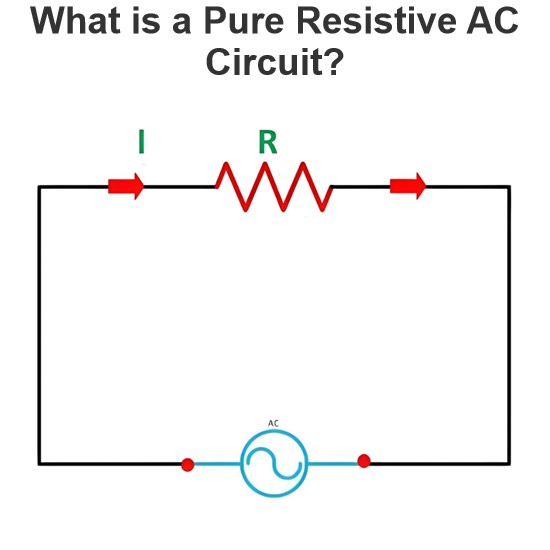
What is a Pure Resistive AC Circuit?
Pure Resistive AC CircuitA circuit containing only a pure resistanceR(in ohms) in an AC system is defined as a Pure Resistive AC Circuit, devoid of inductance and capacitance. Alternating current and voltage in such a circuit oscillate bidirectionally, generating a sine wave (sinusoidal waveform). In this configuration, power is dissipated by the resistor, with voltage and current in perfect phase—both reaching their peak values simultaneously. As a passive component, the resistor neither
Edwiin
06/02/2025
What is a Pure Capacitor Circuit?
Pure Capacitor CircuitA circuit comprising only a pure capacitor with capacitanceC(measured in farads) is termed a Pure Capacitor Circuit. Capacitors store electrical energy within an electric field, a characteristic known ascapacitance(alternatively referred to as a "condenser"). Structurally, a capacitor consists of two conductive plates separated by a dielectric medium—common dielectric materials include glass, paper, mica, and oxide layers. In an ideal AC capacitor circuit, the current
Edwiin
06/02/2025
Resistance Switching in a Circuit Breaker
Resistance SwitchingResistance switching refers to the practice of connecting a fixed resistor in parallel with the contact gap or arc of a circuit breaker. This technique is applied in circuit breakers with high post-arc resistance in the contact space, primarily to mitigate re-striking voltages and transient voltage surges.Severe voltage fluctuations in power systems arise from two main scenarios: interrupting low-magnitude inductive currents and breaking capacitive currents. Such overvoltages
Edwiin
05/23/2025
What is Biot Savart Law?
The Biot-Savart Law is employed to determine the magnetic field intensity dHnear a current-carrying conductor. In other words, it describes the relationship between the magnetic field intensity generated by a source current element. This law was formulated in 1820 by Jean-Baptiste Biot and Félix Savart. For a straight wire, the direction of the magnetic field adheres to the right-hand rule. The Biot-Savart Law is also referred to as Laplace’s law or Ampère’s law.Conside
Edwiin
05/20/2025
Inquiry
Download
IEE-Business is dedicated to serving the personnel in the global power industry.
Join IEE-Business, not only can you discover power equipment and power knowledge, but also canhnd like - minded friends!