Quality Factor of Inductor and Capacitor

Electrical4u
03/11/2024

Quality Factor of Inductor

Every inductor possesses a small resistance in addition to its inductance. The lower the value of this resistance R, the better the quality of the coil. The quality factor or the Q factor of an inductor at the operating frequency ω is defined as the ratio of reactance of the coil to its resistance.

Thus for a inductor, quality factor is expressed as,

Where, L is the effective inductance of the coil in Henrys and R is the effective resistance of the coil in Ohms. As the unit of both resistance and reactance is Ohm, Q is a dimensionless ratio.

The Q factor may also be defined as

Let us prove the above expression. For that let us consider a sinusoidal voltage V of frequency ω radians/seconds applied to an inductor L of effective internal resistance R as shown in Figure 1(a). Let the resulting peak current through the inductor be Im.
Then the maximum energy stored in the inductor

RL and RC circuits
Figure 1. RL and RC circuits connected to a sinusoidal voltage sources
The average power dissipated in the inductor per cycle

Hence, the energy dissipated in the inductor per cycle

Hence,

Quality Factor of a Capacitor

Figure 1(b). shows a capacitor C with small series resistance R associated within. The Q-factor or the quality factor of a capacitor at the operating frequency ω is defined as the ratio of the reactance of the capacitor to its series resistance.
Thus,

In this case also, the Q is a dimensionless quantity since the unit of both reactance and resistance is the same and it is Ohm. Equation (2) giving the alternative definition of Q also holds good in this case. Thus, for the circuit of Figure 1(b), on application of a sinusoidal voltage of value V volts and frequency ω, the maximum energy stored in the capacitor.

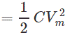
Where, Vm is the maximum value of voltage across the capacitance C.
But if

then
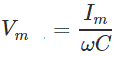
Where, Im is the maximum value of current through C and R.
Hence, the maximum energy stored in capacitor C is

Energy dissipated per cycle

So, the quality factor of capacitor is

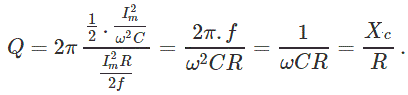
Often a lossy capacitor is represented by a capacitance C with a high resistance Rp in shunt as shown in Figure 2.
Then for the capacitor of Figure 2, the maximum energy stored in the capacitor

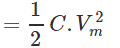
Where, Vm is the maximum value of the applied voltage. The average power dissipated in resistance Rp.


Figure 2. Alternative method of representing a lossy capacitor
Energy dissipated per cycle

Hence,

Source: Electrical4u.

Statement: Respect the original, good articles worth sharing, if there is infringement please contact delete.

Electrical4u

Electrical4U is dedicated to the teaching and sharing of all things related to electrical and electronics engineering.

What is a Pure Resistive AC Circuit?
Pure Resistive AC CircuitA circuit containing only a pure resistanceR(in ohms) in an AC system is defined as a Pure Resistive AC Circuit, devoid of inductance and capacitance. Alternating current and voltage in such a circuit oscillate bidirectionally, generating a sine wave (sinusoidal waveform). In this configuration, power is dissipated by the resistor, with voltage and current in perfect phase—both reaching their peak values simultaneously. As a passive component, the resistor neither
Edwiin
06/02/2025
What is a Pure Capacitor Circuit?
Pure Capacitor CircuitA circuit comprising only a pure capacitor with capacitanceC(measured in farads) is termed a Pure Capacitor Circuit. Capacitors store electrical energy within an electric field, a characteristic known ascapacitance(alternatively referred to as a "condenser"). Structurally, a capacitor consists of two conductive plates separated by a dielectric medium—common dielectric materials include glass, paper, mica, and oxide layers. In an ideal AC capacitor circuit, the current
Edwiin
06/02/2025
Resistance Switching in a Circuit Breaker
Resistance SwitchingResistance switching refers to the practice of connecting a fixed resistor in parallel with the contact gap or arc of a circuit breaker. This technique is applied in circuit breakers with high post-arc resistance in the contact space, primarily to mitigate re-striking voltages and transient voltage surges.Severe voltage fluctuations in power systems arise from two main scenarios: interrupting low-magnitude inductive currents and breaking capacitive currents. Such overvoltages
Edwiin
05/23/2025
What is Biot Savart Law?
The Biot-Savart Law is employed to determine the magnetic field intensity dHnear a current-carrying conductor. In other words, it describes the relationship between the magnetic field intensity generated by a source current element. This law was formulated in 1820 by Jean-Baptiste Biot and Félix Savart. For a straight wire, the direction of the magnetic field adheres to the right-hand rule. The Biot-Savart Law is also referred to as Laplace’s law or Ampère’s law.Conside
Edwiin
05/20/2025
Inquiry
Download
IEE-Business is dedicated to serving the personnel in the global power industry.
Join IEE-Business, not only can you discover power equipment and power knowledge, but also canhnd like - minded friends!