Electrical Engineering Formulas (Most Important Equations)

Electrical4u
03/08/2024

Formulas For Electrical Engineering

Electrical engineering is a branch that deals with the study, design, and implementation of various electrical equipment used in day-to-day life.

It covers a wide range of topics like; power systems, electrical machines, power electronics, computer science, signal processing, telecommunication, control system, artificial intelligence, and many more.

This branch of engineering is full of formulas and concepts (laws) used in many aspects like solving circuits and implementing different equipment to make human life more manageable.

The basic formulas commonly used in various electrical engineering subjects are listed below.

Voltage

Voltage is defined as the electrical potential difference per unit charge between two points in the electric field. The unit of voltage is Volt (V).

(1) \begin{equation*} Voltage (V) = \frac{Work done (W)}{Charge (Q)} \end{equation*}

From the above equation, the unit of voltage is \frac{joule}{coulomb}

Current

Electric current is defined as a flow of charged particles (electrons and ions) moving through a conductor. It is also defined as the flow rate of electric charge through a conducting medium concerning time.

The unit of electric current is ampere (A). And the electric current is denoted mathematically by the symbol ‘I’ or ‘i’.

(2) \begin{equation*} I = \frac{dQ}{dt} \end{equation*}

Resistance

Resistance or electrical resistance measures the opposition to current flow in an electrical circuit. Resistance is measured in ohms (Ω).

Resistance of any conducting material is directly proportional to length of material, and inversely proportional to the area of conductor.

  \[ R \propto \frac{l}{a} \]

(3) \begin{equation*}  R = \rho \frac{l}{a} \end{equation*}

Where, \rho = proportionality constant (specific resistance or resistivity of conducting material)

According to the ohm’s law;

  \[ V \propto I \]

(4) \begin{equation*} Voltage \, V = \frac{I}{R} \, Volt \end{equation*}

Where, R = Resistance of conductor (Ω)

(5) \begin{equation*} Current \, I = \frac{V}{R} \, Ampere \end{equation*}

(6) \begin{equation*} Resistance \, R = \frac{V}{I} Ohm \end{equation*}

Electric Power

Power is the rate of energy supplied or consumed by an electric element with respect to time.

(7) \begin{equation*} P = \frac{dW}{dt} \end{equation*}

For DC System

(8) \begin{equation*} P = VI \end{equation*}

\begin{equation*} P = I^2 R \end{equation*}

For Single-phase System

10) \begin{equation*} P = VI cos \phi \end{equation*}

(11) \begin{equation*} P = I^2 R cos \phi \end{equation*}

(12) \begin{equation*} P = \frac{V^2}{R} cos \phi \end{equation*}

For Three-phase system

(13) \begin{equation*} P = \sqrt{3} V_L I_L cos \phi \end{equation*}

(14) \begin{equation*} P = 3 V_ph I_ph cos \phi \end{equation*}

(15) \begin{equation*} P = 3 I^2 R cos \phi \end{equation*}

(16) \begin{equation*} P = 3 \frac{V^2}{R} cos \phi \end{equation*}

Power Factor

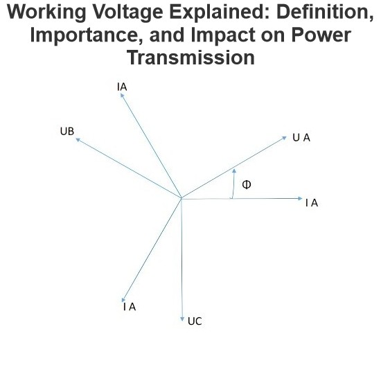
The power factor is a very important term in case of the AC system. It is defined as a ratio of working power absorb by the load to the apparent power flowing through the circuit.

(17) \begin{equation*} Power \, Factor Cos\phi= \frac{Active \, Power}{Apparent \, Power} \end{equation*}

The power factor dimensions less number in the closed interval of -1 to 1. When the load is resistive, power factor is near to 1 and when the load is reactive, power factor is near to -1.

Frequency

Frequency is defined as the number of cycles per unit time. It is denoted as f and measured in Hertz (Hz). One hertz is equal to one cycle per second.

Generally, the frequency is 50 Hz or 60 Hz.

The time period is defined as the time required to produce one complete waveform cycle, denoted as T.

The frequency is inversely proportional to time period (T).

(18) \begin{equation*} F \propto \frac{1}{T} \end{equation*}

Wavelength

Wavelength is defined as a distance between consecutive corresponding points (two adjacent crests, or zero crossing).

It is defined as a ratio of velocity and frequency for sinusoidal waves.

(19) \begin{equation*} \lambda = \frac{v}{f} \end{equation*}

Capacitance

A capacitor stores electrical energy in an electric field when voltage is supplied. The effect of capacitors in electrical circuits is known as capacitance.

The electric charge Q accumulated in capacitor is directly proportional to the voltage developed across the capacitor.

 \[ Q \propto V\]

  \[ Q = CV \]

(20)\begin{equation*} C = \frac{Q}{V} \end{equation*}

The capacitance depends on the distance between two plates (d), area of plate (A), and permittivity of dielectric material.

(21) \begin{equation*} C = \frac{\epsilon A}{d} \end{equation*}

Inductor

An inductor stores electrical energy in the form of a magnetic field when electric current flows through it. Sometimes, an inductor is also known as coil, reactor, or chokes.

The unit of inductance is henry (H).

The inductance is defined by a ratio of magnetic flux linkage (фB), and the current passes through the inductor (I).

(22) \begin{equation*} L = \frac{\phi_B}{I} \end{equation*}

Electric Charge

Electric charge is a physical property of substance. When any matter is placed in an electromagnetic field, it will experience a force.

Electric charges can be positive (proton) and negative (electron), measured in coulomb and denoted as Q.

One coulomb is defined as the quantity of charge transferred in one second.

(23) \begin{equation*} Q = IT \end{equation*}

Electric Field

An electric field is a field or space around an electrically charged object where any other electrically charged object will experience a force.

An electric field is also known as electric field intensity or electric field strength, denoted by E.

Electric field is defined as a ratio of electrical force per test charge.

(24)
\begin{equation*} E = \frac{F}{Q} \end{equation*}

For parallel plate capacitor, the voltage difference between two plates is expressed a work done on a test charge Q to move from the positive plate to negative plate.


  \[ V = \frac{Work done}{charge} = \frac{Fd}{Q} = Ed \]

(25) \begin{equation*} E = \frac{V}{d} \end{equation*}

Electric Force

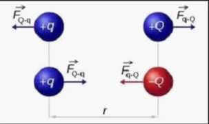
When a charged object enters the electric field of another charged object, it experiences a force as per Coulomb’s law.

Coulomb’s Law.png

As shown in the above figure, a positively charged object is placed in space. If both objects have the same polarity, objects repel each other. And if both objects have different polarities, objects attract each other.

According to coulomb’s law,

(26) \begin{equation*} F = \frac{Q_1 Q_2}{4 \pi \epsilon_0 d^2 } \end{equation*}

According to coulomb’s law, the equation of electric field is;

  \[ E = \frac{F}{Q} = \frac{kQq}{Qd^2} \]

(27) \begin{equation*} E = \frac{kq}{d^2} \end{equation*}

Electric Flux

According to gauss’s law, the equation of electric flux is;

(28) \begin{equation*} \phi = \frac{Q}{\epsilon_0} \end{equation*}

DC Machine

Back EMF

(29) \begin{equation*} E_b = \frac{P \phi NZ}{60A} \end{equation*}

Losses in DC Machine

Copper loss

The copper losses occur due to current flowing through the windings. The copper loss is directly proportional to the square of current flowing through the winding, and is also known as I2R loss or ohmic loss.

Armature copper loss: I_a^2 R_a

Shunt field copper loss: I_{sh}^2 R_{sh}

Series field copper loss: I_{se}^2 R_{se}

Copper loss in interpole: I_a^2 R_i

Brush contact loss: I_a^2 R_b

Hysteresis Loss

Hysteresis loss occurs due to the reversal of magnetism of the armature core.

(30) \begin{equation*} P_h = \eta B_{max}^1.6 f V \end{equation*}


Eddy Current Loss

The power loss that occurs due to eddy current flow is known as eddy current loss.

(31) \begin{equation*} P_e = K B_{max}^2 f^2 t^2 V \end{equation*}

Transformer

EMF Equation

(32) \begin{equation*} E = 4.44 \phi_m f T \end{equation*}

Turns Ratio

(33) \begin{equation*} \frac{E_1}{E_2} = \frac{T_1}{T_2} = \frac{V_1}{V_2} = \frac{I_2}{I_1} = a \end{equation*}

Voltage Regulation

(34) \begin{equation*} V.R. = \frac{E_2 - V_2}{V_2} \end{equation*}

Induction Motor

Synchronous Speed

(35) \begin{equation*} N_s = \frac{120f}{P} \end{equation*}

Torque Equation

Developed Torque

(36) \begin{equation*} T_d = \frac{k s E_{20}^2 R_2}{R_2^2 + s^2 X_{20}^2} \end{equation*}

Shaft Torque

(37) \begin{equation*} T_{sh} = \frac{3 E_{20}^2 R_2}{2 \pi n_s (R_2^2 + X_{20}^2) } \end{equation*}

Winding EMF

(38) \begin{equation*} E_1 = 4.44 k_{w1} f_1 \phi T_1 \end{equation*}

(39) \begin{equation*} E_2 = 4.44 k_{w2} f_1 \phi T_2 \end{equation*}

Where,

Kw1, Kw2 = Winding factor of stator and rotor, respectively

T1, T2 = Number of turns in stator and rotor winding

Source: Electrical4u.

Statement: Respect the original, good articles worth sharing, if there is infringement please contact delete.


Electrical4u

Electrical4U is dedicated to the teaching and sharing of all things related to electrical and electronics engineering.

What is a Pure Resistive AC Circuit?
Pure Resistive AC CircuitA circuit containing only a pure resistanceR(in ohms) in an AC system is defined as a Pure Resistive AC Circuit, devoid of inductance and capacitance. Alternating current and voltage in such a circuit oscillate bidirectionally, generating a sine wave (sinusoidal waveform). In this configuration, power is dissipated by the resistor, with voltage and current in perfect phase—both reaching their peak values simultaneously. As a passive component, the resistor neither
Edwiin
06/02/2025
What is a Pure Capacitor Circuit?
Pure Capacitor CircuitA circuit comprising only a pure capacitor with capacitanceC(measured in farads) is termed a Pure Capacitor Circuit. Capacitors store electrical energy within an electric field, a characteristic known ascapacitance(alternatively referred to as a "condenser"). Structurally, a capacitor consists of two conductive plates separated by a dielectric medium—common dielectric materials include glass, paper, mica, and oxide layers. In an ideal AC capacitor circuit, the current
Edwiin
06/02/2025
Resistance Switching in a Circuit Breaker
Resistance SwitchingResistance switching refers to the practice of connecting a fixed resistor in parallel with the contact gap or arc of a circuit breaker. This technique is applied in circuit breakers with high post-arc resistance in the contact space, primarily to mitigate re-striking voltages and transient voltage surges.Severe voltage fluctuations in power systems arise from two main scenarios: interrupting low-magnitude inductive currents and breaking capacitive currents. Such overvoltages
Edwiin
05/23/2025
What is Biot Savart Law?
The Biot-Savart Law is employed to determine the magnetic field intensity dHnear a current-carrying conductor. In other words, it describes the relationship between the magnetic field intensity generated by a source current element. This law was formulated in 1820 by Jean-Baptiste Biot and Félix Savart. For a straight wire, the direction of the magnetic field adheres to the right-hand rule. The Biot-Savart Law is also referred to as Laplace’s law or Ampère’s law.Conside
Edwiin
05/20/2025
Inquiry
Download
IEE-Business is dedicated to serving the personnel in the global power industry.
Join IEE-Business, not only can you discover power equipment and power knowledge, but also canhnd like - minded friends!