• Product
  • Suppliers
  • Manufacturers
  • Solutions
  • Free tools
  • Knowledges
  • Experts
  • Communities
Search


Bleeder Resistor: What is it, and Why is it Used?

Electrical4u
Field: Basic Electrical
0
China

What is a Bleeder Resistor?

A bleeder resistor is a standard resistor connected in parallel with the output of a high-voltage power supply circuit for the purpose of discharging the electric charge stored in the power supply’s filter capacitors when the equipment is turned OFF. This is done for safety reasons.

If someone accidentally touches during the service of equipment in the OFF state, there may be a chance to get shocked even if the device is in OFF condition. Hence, it is necessary to discharge the capacitor for safety purposes. The bleeder resistor is hence used to help prevent unwanted electrical discharges.

Importance of Bleeder Resistor in a Circuit

To know the importance of a bleeder resistor, we need a circuit that used a filter. For example, we choose a full-wave rectifier circuit. The output of the rectifier is not pure DC signal. It is pulsating DC signal and this supply cannot directly give to the load.

So, we use a filter circuit to make the output of the rectifier pure DC signal. And the filter consists of the capacitors and inductors. The below circuit shows that the output of the rectifier is given to the load via the filter circuit and bleeder resistor.

Importance of Bleeder Resistor in Circuit

As shown in the above figure, the bleeder resistor is connected in parallel with the capacitor. The capacitor is charged at peak value during the device is in ON condition. And if we turn OFF the device, some amount of charge is still saved by that capacitor.

Now if the bleeder resistor is not connected and someone touched the terminals, the capacitor will discharge through that person. And that person will get shocked.

But if we connect a standard resistor in parallel with that capacitor, the capacitor will discharge through the resistor.

How to Choose a Bleeder Resistor

If you select a small valued resistor, it will provide high-speed bleeding. But it consumes more power. And if you select a high valued resistor, it will cause less power loss but bleeding speed is less.

So, the designer has to select a properly valued resistor that is high enough to not interfere with the power supply and low enough to discharge the capacitor in a short time.

To calculate the appropriate value of the bleeder resistor, consider the relationship among the momentary voltage across capacitor Vt, the bleeder resistor (R), and the initial value Vu. The total capacitance is C and the momentary period is t. Then you can calculate the value of bleeder resistance from the below equation.

  \[ V_t = V_u e^{\frac{-t}{RC} \]

  \[ \frac{V_t}{V_u} =  e^{\frac{-t}{RC} \]

  \[ ln(\frac{V_t}{V_u}) = \frac{-t}{RC} \]

  \[ R = \frac{-t}{C \times  ln(\frac{V_t}{V_u})} \]

In the above equation, keep the value of momentary voltage low for safety purposes. But if you make it zero, the time required for the bleeder resistor to discharge capacitor is infinite. Hence the designer has to put the proper value of safe voltage and time required to discharge a capacitor.

\[ P = \frac{V_0^2}{R} \]

Now if you select a value of bleeder resistor for fast discharge, resistance will very low. And it will increase the power loss. In the above equation, V0 is the initial voltage, and P is the power consumed by the bleeder resistance.

Hence, the designer has to decide the desired value for the power loss and bleeding speed of resistor.

Applications of Bleeder Resistors

The bleeder resistor is used in the circuit for safety purposes. But it is also useful to improve the voltage regulation and a tapped resistor used as a voltage divider.

Voltage Regulation

The voltage regulation is defined as the ratio of the difference between no-load and full-load voltage to no-load voltage. The equation of voltage regulation is as shown in the below equation.

  \[ V_r = \frac{V_0 - V_f}{V_f} \]

Where V0 is no-load voltage and Vf is a full-load voltage. For good voltage regulation, the value of Vr is kept as low as possible.

Now if the bleeder resistor is connected in parallel with a filter capacitor and load resistor. Therefore, the voltage drop occurs in load resistance as well as in bleeder resistance.

When supply is given, the voltage drop across the load resistance comes into the picture. But, when supply is OFF, the voltage drop across the bleeder resistance comes into the picture. Hence, it increases the value of the no-load voltage.

Therefore, it will decrease the value of the difference of no-load voltage and full-load voltage that improves the voltage regulation of the circuit.

Voltage Division

If you want multiple voltage arrangements in your circuit, a tapped resistor is used as a bleeder resistor. The circuit arrangement is as shown in the below figure.

Bleeder Resistor as Voltage Divider

As shown in the above figure, the bleeder resistor has three tapings. By using proper tapping, we can have three different voltage across the load. Therefore, this provides a function of a voltage divider.

Safety Purposes

The main function of the bleeder resistor is safety. It is used to discharge the capacitor after the device is turned OFF. The circuit arrangement for this is as shown in the below figure.

Bleeder Resistor for Safety Purpose

The filter consists of inductors and capacitors. The bleeder resistors are used to connect it with parallel to the filter capacitor. Once the device is turned OFF, some amount of charge is stored inside the capacitor.

This charged capacitor may discharge through the person. And that person may get shocked. Hence, a bleeder resistor is used to connect in parallel with the capacitor to discharge it after the device is turned OFF.

Source: Electrical4u.

Statement: Respect the original, good articles worth sharing, if there is infringement please contact delete.
Give a tip and encourage the author!
Recommended
Difference Between Electromagnet and Permanent Magnet
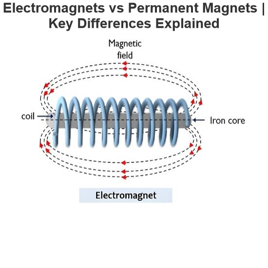
Electromagnets vs. Permanent Magnets: Understanding the Key DifferencesElectromagnets and permanent magnets are the two primary types of materials that exhibit magnetic properties. While both generate magnetic fields, they differ fundamentally in how these fields are produced.An electromagnet generates a magnetic field only when an electric current flows through it. In contrast, a permanent magnet inherently produces its own persistent magnetic field once it has been magnetized, without requirin
Edwiin
08/26/2025
Working Voltage in Power System
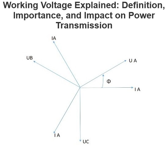
Working VoltageThe term "working voltage" refers to the maximum voltage that a device can withstand without sustaining damage or burning out, while ensuring the reliability, safety, and proper operation of both the device and associated circuits.For long-distance power transmission, the use of high voltage is advantageous. In AC systems, maintaining a load power factor as close to unity as possible is also economically necessary. Practically, heavy currents are more challenging to handle than hi
Encyclopedia
07/26/2025
What is a Pure Resistive AC Circuit?
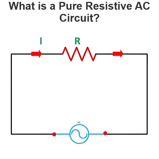
Pure Resistive AC CircuitA circuit containing only a pure resistanceR(in ohms) in an AC system is defined as a Pure Resistive AC Circuit, devoid of inductance and capacitance. Alternating current and voltage in such a circuit oscillate bidirectionally, generating a sine wave (sinusoidal waveform). In this configuration, power is dissipated by the resistor, with voltage and current in perfect phase—both reaching their peak values simultaneously. As a passive component, the resistor neither
Edwiin
06/02/2025
What is a Pure Capacitor Circuit?
Pure Capacitor CircuitA circuit comprising only a pure capacitor with capacitanceC(measured in farads) is termed a Pure Capacitor Circuit. Capacitors store electrical energy within an electric field, a characteristic known ascapacitance(alternatively referred to as a "condenser"). Structurally, a capacitor consists of two conductive plates separated by a dielectric medium—common dielectric materials include glass, paper, mica, and oxide layers. In an ideal AC capacitor circuit, the current
Edwiin
06/02/2025
Seed Inquiry
Download
Get the IEE Business Application
Use the IEE-Business app to find equipment, obtain solutions, connect with experts, and participate in industry collaboration anytime, anywhere—fully supporting the development of your power projects and business.