
For the purpose of accurately representing a specific electrical system or circuit in Electrical and Electronics Engineering, many forms of drawings and diagrams are used.
These electrical circuits are shown using lines, which stand in for wires, and symbols or icons, which are used to represent the various electrical & electronic components.
It is helpful to acquire a better knowledge of the link between the various components. When wiring a structure, electricians will make use of something called an electrical floor plan, which is also known as an electrical diagram.
The connection between electrical devices and equipment will be shown on an electrical drawing for the operation of machinery and maintenance procedures. The electrical devices & their connections are the only components of this electrical drawing.
The actual circuit and its purpose remain the same, although the possibility that engineers can highlight certain parts of the system using numerous types of electrical drawings.
There are many types of electrical drawings, including:
1). Block Diagram
2). Schematic Diagram
3). One-line Diagram or Single Line Diagram
4). Wiring Diagram
5). Pictorial Diagram (Diagram in Pictures)
6). Line Diagram or Ladder Diagram
7). Logic Diagram
8). Riser Diagram
9). Electrical Floor Plan
10). IC Layout Diagram

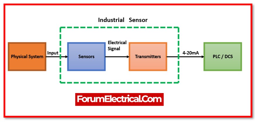
The first step in constructing a complicated circuit for any project is to create a block diagram since they are simpler to create. It is deficient in details on component placement and wiring.
It ignores any minor components and entirely illustrates the system’s major parts. Consequently, block diagrams are not used by electricians.
The symbols and lines used to represent the components in an electrical circuit’s schematic design illustrate all of the electrical connections between them.
Similar to wiring diagrams, it does not describe the actual locations of the components, and the distances between them are not represented by the lines connecting the components.
It facilitates in illuminating the components’ accurate terminal connections as well as their series and parallel connections.
Applying electrical circuit theory will make troubleshooting a specific schematic simple.

It is the most prevalent kind of electrical drawing & is mostly used by technicians to implement electrical circuits.
When creating different electrical projects, the majority of engineering students depend on schematic diagrams.
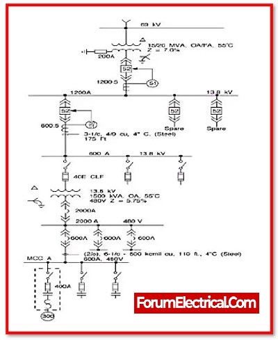
A single-line diagram (SLD) (or) one-line diagram is a single-line visual representation of an electrical circuit. A single line, as the name implies, is used to signify many power lines, such as in a three-phase system.
.jpg")
The electrical connections of the components are not shown in a single line diagram, but it may display the size and ratings of the components utilised.
It simplifies complicated three-phase power circuits by displaying all of the electrical components & their connections.
During troubleshooting, they are utilised to identify and isolate any defective equipment in a power system.
The SLD diagram employs electrical symbols and icons for various components.

The wiring diagram depicts electrical parts in their approximate physical position using specified symbols & their interconnections through lines.
Wires are represented by vertical and horizontal lines, and each line symbolises a single wire that links electrical components.
A wiring diagram depicts a visual representation of the components in such a way that it mimics their electrical connection, arrangement, and location in a genuine circuit.
It is very useful in displaying the interconnections in different components such as electrical panels and distribution boxes, which are often used for wire installation in homes and workplaces.
This is a wiring schematic for a three-phase house wiring arrangement. It clearly depicts the components and their electrical connections.
Each line (with a colour code) symbolises a particular phase wire & its connection to each component.
These schematics are used by electricians to install wiring in homes.

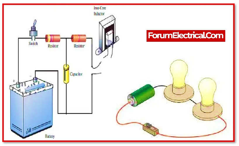
The visual representation may not always accurately represent the true circuit. In practical terms, it depicts the circuit’s visual look in real time.
It is not often utilised since it is not able to understand (or) troubleshoot an actual circuit. It is hard for someone with little electrical understanding to analyse and diagnose the circuit.

The visual depiction does not give adequate information about the components’ electrical connections.


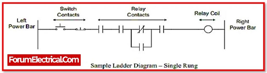
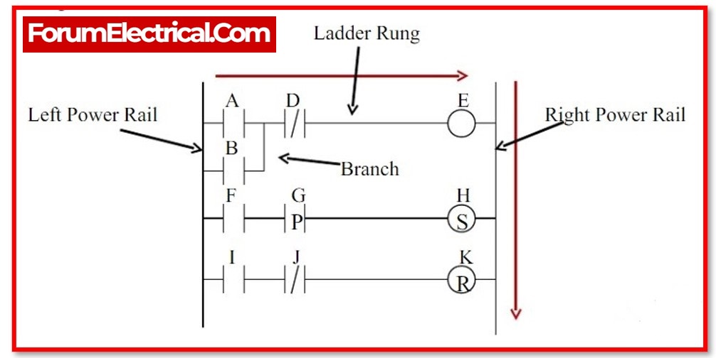
Ladder diagrams are the electrical diagrams that are used in industries to illustrate control logic systems. It is known as ladder diagram because it resembles a ladder.
The power rail (or) voltage source is represented by the left vertical line, while the ground or neutral is represented by the right vertical line.
Each horizontal row resembles a rung, which is a parallel circuit.

A ladder diagram is basic, easy to read, and it helps in speedy circuit troubleshooting.
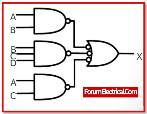
A logic diagram shows a complicated circuit & process using multiple blocks or symbols to depict a logic circuit. The logic symbols indicate the logic functions, while the blocks represent sophisticated logic circuits.
For easier understanding without learning the underlying structure, these blocks are labelled with their logic function.

The blocks are linked together by lines that represent the signal’s input and output lines.
The logic diagram fails to represent the electrical properties of a circuit, such as current, voltage, or power, among other things.
It just indicates the logical function of the circuit (or) device in binary representation,
i.e., 1 or 0.
Logic diagrams are often utilised in the design of digital logic.
The riser diagram depicts the actual arrangement of power distribution in a multi-storey building with a single line. It indicates the
Size of conduits,
Wire size,
Circuit breaker rating, and
Other electrical equipment (rating of switches, plugs, outlets, and so on)
from the point of entry to the tiny circuit branches on each level.
Its arrangement is similar to that of an alarm system, and it also includes telecom & internet connections.
The riser diagram obtained the term because it depicts the transfer of electricity from one level to the next.
It does not provide any additional information and does not indicate the actual location of the device.

It primarily focuses on providing electrical power to the various appliances on each floor of a structure.
It explains how the building’s
Lighting,
Heating, and
Ventilation systems function,
and if there are any hazards, they are simply rectified.
Electrical professionals depend on a building’s riser diagram to prevent possible electrical risks.
It is a vertical illustration of numerous appliances in a building, such as
Lights,
Switches, and
Fans.
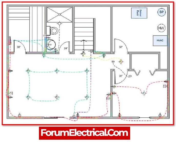
It details their exact placement, as well as their size & distance from each wall & ceiling. It shows a miniature representation of each area from above.
It often includes a description which presents a visual representation of the symbols used.


When wiring a newly constructed building or rewiring an existing one, electrical contractors will need individual floor plans for each level of a multi-story structure.
These floor plans will also be used when the buildingis being rewired.
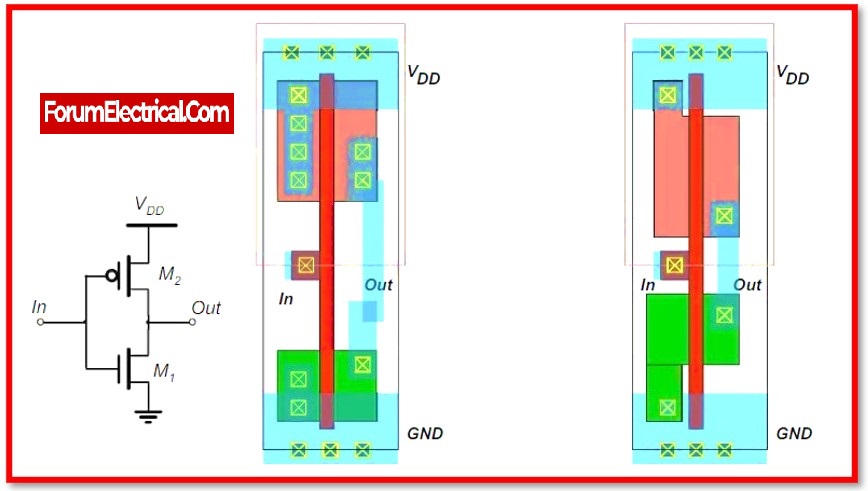
The interior design of a semiconductor component is referred to as the IC layout diagram (or) IC (mask) layout.
An integrated circuit (IC) is made up of many layers (or) masks of metal, oxide, and semiconductor material.
It illustrates the shape and also the size and connectivity of several semiconductor layers.
It defines the internal structure of integrated circuits and is utilised in their production and design.

What are rungs in ladder diagram?
The cables & input devices that either let or block current flow to the output devices make up the ladder’s rungs.
When viewed alongside rail lines, these lines could seem narrow. One can select the sequence of occurrences that either energises (or) de-energizes the outputs based on where the input & output devices are placed.
Accurate troubleshooting depends on being able to identify this series of occurrences.
Typically, output devices are positioned on the right side of the rungs, while input devices are positioned on the left.
Statement: Respect the original, good articles worth sharing, if there is infringement please contact delete.


