
Search


Auxiliary contact in switchgears

Auxiliary contacts in circuit breakers: functions, types, and control applications for electrical systems.

Edwiin
Field: Power switch
10Year<
China
Add us on Google

Auxiliary contacts are essential components in circuit breakers and switchgear, providing critical functionality for control and indication. Here's a breakdown of their purpose and operation:

Purpose of Auxiliary Contacts:

  1. Breaker Trip & Closing Control:

    • Auxiliary contacts are used in control circuits to manage the supply to the trip coil and closing coil, ensuring proper operation of the circuit breaker.

  2. Breaker ON/OFF Indication:

    • These contacts provide signals to indicate whether the breaker is in the ON (closed) or OFF (open) position.

  3. Integration with Relays and SCADA:

    • Auxiliary contacts are connected to devices like the Trip Circuit Supervision (TCS) relay, busbar relay, and SCADA systems for monitoring and control purposes.

  4. Customer Use:

    • Contacts not used in control circuits are typically made available to customers for custom applications.

Types of Contacts:

  1. NO (Normally Open) Contact:

    • Open when the device is not energized or in its default state.

    • Closes when the device is energized or activated.

  2. NC (Normally Closed) Contact:

    • Closed when the device is not energized or in its default state.

    • Opens when the device is energized or activated.

  3. NOC (Normally Open-Closed) Contact (Change-Over Contact):

    • A combination of NO and NC contacts with a common backside.

    • When the device changes position, the NO contact closes, and the NC contact opens simultaneously.

Operation of Auxiliary Switch:

  • When the auxiliary switch operates, its contacts change their status:

    • Open contacts become closed.

    • Closed contacts become open.

  • This change in status is used for various control and indication functions in the circuit breaker.

Typical Quantities of Auxiliary Contacts:

  • Auxiliary switches are often provided in standard configurations, such as:

    • 12 NO + 12 NC

    • 18 NO + 18 NC

    • 20 NO + 20 NC

Circuit Diagram Representation:

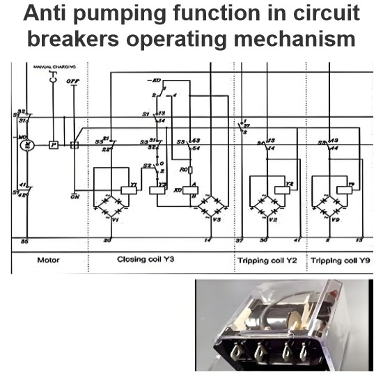
  • In the circuit diagram, the auxiliary switch is typically shown with its NO, NC, and NOC contacts, illustrating how they interact with the breaker's operating mechanism.

Give a tip and encourage the author!

Comments

Share your question or perspective
WhatsApp
Send inquiry
+86
Click to upload file
Download
Get the IEE Business Application
Use the IEE-Business app to find equipment, obtain solutions, connect with experts, and participate in industry collaboration anytime, anywhere—fully supporting the development of your power projects and business.
Login
or continue with
New here?
Register