This method involves injecting or superimposing a current in the opposite direction of the current to be interrupted. The superimposed current can be provided through interaction with a parallel resonant circuit or by actively injecting current, thereby creating an artificial current zero crossing. Once the artificial current zero crossing is achieved, the interruption process is similar to that in an AC circuit.
Working Principle
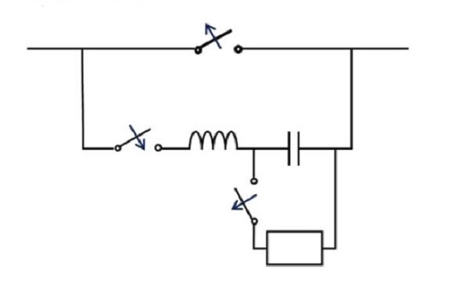
The diagram below illustrates the scheme of actively injecting a current in the opposite direction to the system current, thereby generating a current zero crossing. The specific steps are as follows:
Pre-charging Stage:
Interruption Process:
The interruption process begins by first opening the contacts of the switch in the main circuit.
Then, the switch in the parallel circuit is closed.
This causes the capacitor to discharge, and its current is superimposed on the current in the main circuit.
If the amplitude of the capacitor discharge current exceeds the amplitude of the current in the main circuit, an artificial current zero crossing is created, thus interrupting the current.
Key Requirements
Since the opening time of the switching device is only a few milliseconds, the mechanical switch must open very quickly. For this purpose, solid-state switching devices can be used in the main path to ensure rapid and reliable response.
Diagram Explanation
The diagram illustrates the specific implementation of this process:
Main Circuit: Contains the current to be interrupted.
Capacitor: Pre-charged by a separate charging unit.
Parallel Circuit: Contains a switch to control the discharge of the capacitor.
Solid-State Switch: Used to quickly open the contacts of the switch in the main circuit.
Summary
By using this method, an artificial current zero crossing can be effectively generated in the main circuit, thereby achieving current interruption. This method not only improves the reliability of current interruption but also reduces the stress on the switching device, extending its lifespan. Using solid-state switching devices further enhances the system's rapid response capability, ensuring efficient and safe current interruption.

 Login