1. Wiring Forms of Ring - Main Unit
1.1 Composition of Ring - Main Unit
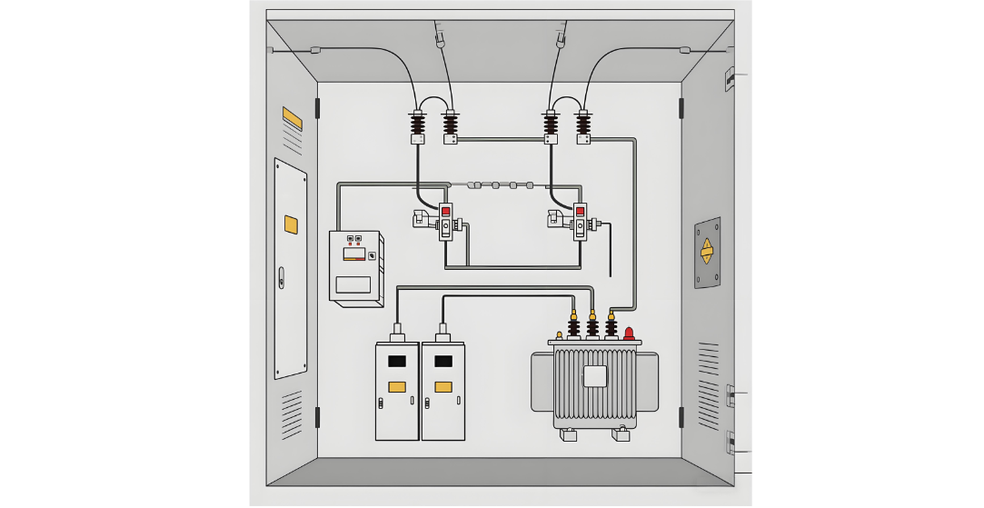
The Ring - Main Unit (RMU) is composed of compartments. Generally, it has at least three compartments, including two compartments for ring cable entry and exit and one compartment for the transformer circuit.
1.2 Configuration of Protection Modes for Ring - Main Unit
Both the ring cable feeder compartments and the transformer feeder compartments adopt load switches, usually three - position load switches with functions of making, breaking, and grounding. The transformer feeder compartments are also equipped with high - breaking - capacity backup current - limiting fuses for protection. Practical operation has proven that this is a simple, reliable, and economical power distribution method.
1.3 Characteristics of Protection Configuration for Ring - Main Unit
The load switch is used to switch rated load currents. It has characteristics such as simple structure and low cost, but it cannot interrupt short - circuit currents. The high - breaking - capacity backup current - limiting fuse serves as a protective element and can interrupt short - circuit currents. Combining these two elements organically can meet the operation and protection requirements of the power distribution system under various normal and fault operation modes. The determination of circuit breaker parameters and the design and manufacturing of its structure are carried out in strict accordance with standards.
It has both operation and protection functions, so its structure is complex and its cost is high, making large - scale use impractical. In ring - main units, a large number of load switch and high - breaking - capacity backup fuse combination devices are used. The operation and protection functions for electrical equipment, which are not exactly the same, are realized by two simple and inexpensive components. That is, the load switch is used to complete a large number of load switching operations, while the high - breaking - capacity backup current - limiting fuse is used to protect equipment where short - circuits rarely occur. This well - solves the problem, avoiding the use of complex and expensive circuit breakers while meeting the actual operation requirements.
Circuit breakers have all protection and operation functions, but they are expensive.
Load switches have basically the same performance as circuit breakers, but they cannot interrupt short - circuit currents.
The combination of a load switch and a high - breaking - capacity backup current - limiting fuse can interrupt short - circuit currents. The breaking capacity of some fuses is even higher than that of circuit breakers. Therefore, using this combination is no less effective than using a circuit breaker, but the cost can be greatly reduced.
1.4 Advantages of the Combination of Load Switch and High - Breaking - Capacity Backup Fuse
The combination of a load switch and a high - breaking - capacity fuse has the following advantages:
1.4.1 Good Performance in Switching No - Load Transformers
Most of the loads in ring - main units are distribution transformers. Generally, the capacity is not more than 1250 KVA, and in rare cases, it reaches 1600 KVA. The no - load current of a distribution transformer is generally about 2% of the rated current, and the no - load current of a larger distribution transformer is smaller. When the ring - main unit switches the small current of a no - load transformer, it performs well and does not generate a high overvoltage.
1.4.2 Effective Protection of Distribution Transformers
Especially for oil - immersed transformers, using a load switch with a high - breaking - capacity backup current - limiting fuse is more effective than using a circuit breaker. Sometimes, the latter may not even provide effective protection. Relevant information shows that when an oil - immersed transformer has a short - circuit fault, the pressure generated by the arc rises, and the bubbles formed by oil vaporization will occupy the space originally belonging to the oil. The oil will transfer the pressure to the transformer oil tank. As the short - circuit continues, the pressure further increases, causing the oil tank to deform and crack.
To avoid damaging the oil tank, the fault must be cleared within 20 ms. If a circuit breaker is used, due to the presence of relay protection, plus its own operation time and arc - extinguishing time, the total opening time is generally not less than 60 ms, which cannot effectively protect the transformer. However, the high - breaking - capacity backup current - limiting fuse has a quick - breaking function. Coupled with its current - limiting function, it can clear the fault and limit the short - circuit current within 10 ms, effectively protecting the transformer. Therefore, high - breaking - capacity backup current - limiting fuses should be used to protect electrical equipment as much as possible instead of circuit breakers. Even if the load is a dry - type transformer, the fuse protection acts quickly and is better than using a circuit breaker.
1.4.3 In Terms of Coordination of Relay Protection
In most cases, there is no need to use a circuit breaker in the ring - main unit. This is because the protection settings of the circuit breaker at the head end of the ring distribution network (i.e., the 10KV feeder circuit breaker in a 110KV or 220KV substation) are generally as follows: the time for instantaneous protection is 0s, the time for over - current protection is 0.5s, and the time for zero - sequence protection is 0.5s. If a circuit breaker is used in the ring - main unit, even if the setting time is 0s for operation, due to the dispersion of the inherent operation time of the circuit breaker, it is difficult to ensure that the circuit breaker in the ring - main unit, rather than the upper - level circuit breaker, acts first.
1.4.4 High - Breaking - Capacity Backup Current - Limiting Fuse Can Provide Protection for Downstream Equipment
Such as current transformers, cables, etc. The protection range of the high - breaking - capacity backup current - limiting fuse can be from the minimum melting current (usually 2 - 3 times the rated current of the fuse) to the maximum breaking capacity. The current - time characteristic of the current - limiting fuse is generally a steep inverse - time curve. After a short - circuit occurs, it can melt and clear the fault in a very short time. If a circuit breaker is used for protection, it will inevitably greatly increase the thermal stability requirements of other electrical components such as cables, current transformers, and transformer bushings, increasing the cost of electrical equipment and the project cost. Here, it should be pointed out that when using the combination of a load switch and a high - breaking - capacity backup fuse, the two should be well coordinated. When the fuse does not melt in three phases, the striker of the fuse should immediately trip the load switch to prevent single - phase operation.
2. Wiring Forms of High - Voltage Chambers for Terminal Users
The standard GB14285 - 1993 "Technical Code for Relaying Protection and Safety Automatic Devices" stipulates that when selecting the protective switchgear for a distribution transformer, when the capacity is equal to or greater than 800 KVA, a circuit breaker with a relaying protection device should be selected. This regulation can be understood based on the following two aspects of needs:
When the capacity of the distribution transformer reaches 800 KVA and above, in the past, most of them were oil - immersed transformers and were equipped with gas relays. Using a circuit breaker can cooperate with the gas relay to effectively protect the transformer.
For users with a device capacity greater than 800 KVA, due to various reasons, a single - phase grounding fault may cause the zero - sequence protection to act, causing the circuit breaker to trip and isolate the fault, so as not to cause the feeder circuit breaker of the main substation to act and affect the normal power supply of other users. In addition, the standard also clearly stipulates that even if a single transformer does not reach this capacity, but if the total capacity of the user's distribution transformers reaches 800 KVA, this requirement should also be met. At present, the wiring scheme of most users' high - voltage switchgear rooms is a basic wiring method, and based on this, wiring methods such as one - main - one - standby incoming lines or double incoming lines with busbar sectioning can be derived.
3. Conclusion
The protection configurations for 10kV distribution transformers mainly include circuit breakers, load switches, or load switches with fuses. Considering technical, economic performance, and operation management factors comprehensively, whether in a 10kV ring - main unit or a high - voltage power distribution unit for terminal users, the protection configuration of a load switch combined with a high - breaking - capacity backup current - limiting fuse can not only provide rated load current but also interrupt short - circuit currents and has the performance of switching no - load transformers, which can effectively protect distribution transformers. Therefore, the configuration of a load switch combined with a high - breaking - capacity backup current - limiting fuse is recommended as the protection mode for distribution transformer protection.