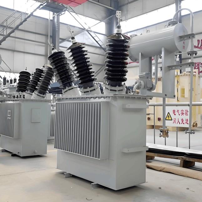
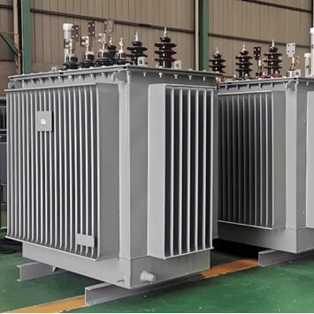
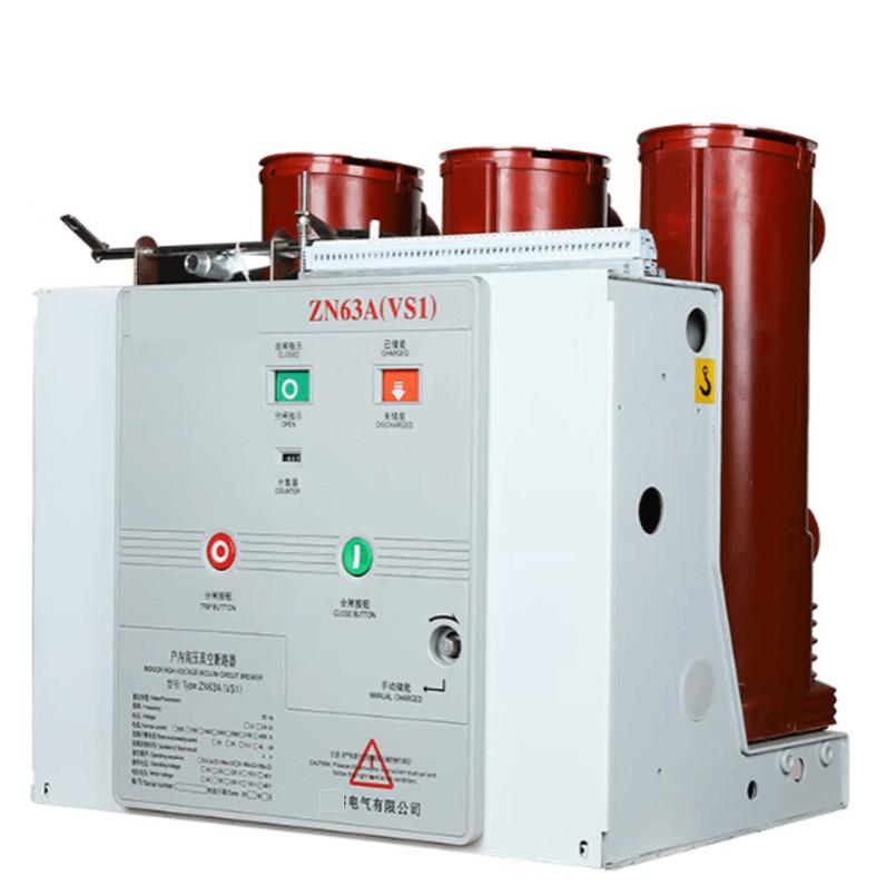
Salamu kwa wote! Mimi ni James, mtazamaji wa ujuzi zaidi ya miaka kumi katika kutengeneza mabadiliko wa umbo wa umeme. Leo, nikitaka kuzungumzia kuhusu utambulisho na kutengeneza mabadiliko wa umbo wa umeme wa Air Insulated Switchgear (AIS) katika steshoni za nje za 66kV.
Vifaa hivi ni muhimu sana kwa usimamizi na usalama katika mifumo ya umeme. Utambulisho na kutengeneza sahihi yao ina athari kubwa kwa usalama na ustawi wa mkoa wa umeme mzima. Kwa maendeleo ya teknolojia ya mitandao ya umeme smart, mabadiliko wa umbo wa umeme wa AIS electronics zinapata chaguo la mapenzi zaidi. Wanaweza kuwepo na vipengele vya akili mengi, lakini pia wanaweza kukusanya malengo magumu za kutengeneza na kudhibiti.
1. Vidakika Muhimu katika Kutambua Mabadiliko ya Umbo wa Umeme wa AIS
Hebu tianze na fanya na matumizi — hii ni kipaumbele muhimu sana katika kutambua mabadiliko ya umbo wa umeme.
Mabadiliko ya umbo wa umeme wa usalama unahitaji uwiano mkubwa wa kiwango. Mara nyingi, tunachagua daraja la usahihi 10P na uwezo wa asili wa karibu 5VA. Hii hutayari kutekeleza taarifa sahihi hata kwenye mazingira isiyofaa kama ukuta wa mwisho.
Mabadiliko ya umbo wa umeme ya usimamizi, kwa upande mwingine, yanahitaji usahihi mkubwa. Tunaenda mara moja tu daraja la 0.2S au zaidi, na uwezo wa asili wa asili wa karibu 10VA, ili kufanikiwa kwa mahitaji ya usimamizi wa nishati na usimamizi wa mfumo.
Kutokana na maendeleo ya mitandao ya umeme smart, mabadiliko ya umbo wa umeme electronics zinapata chaguo la mapenzi zaidi katika steshoni za 66kV kwa sababu ya uwezo wao wa kupatikana digital, hasa katika mazingira ambayo yanahitaji ufungaji na mifumo ya usalama digital.
Angalia sasa kiwango cha umeme na muundo. Katika 66kV, ambayo ndiyo sehemu ya kiwango cha umeme cha chini (3kV–110kV), muundo wa umbo moja au tatu husikuwa wazi.
Kwa mifumo rasmi ya kawaida, mabadiliko miwili ya umbo moja vilivyotengenezwa kati ya umbo la umeme au V/V hunafanya vizuri.
Katika steshoni ambazo zinahitaji usimamizi wa insulation, ni bora kutumia umbo wa umbo tatu na namba tano au mabadiliko miwili ya umbo moja vilivyotengenezwa kati ya Y/Y-Δ. Muundo huu unaweza kusaidia kwa uzito wa umeme wa umbo na kuchuja zero-sequence voltage kupitia open delta winding, kusaidia kwa kutosha usimamizi wa hali ya insulation ya mfumo.
Kisha kuna aina ya insulation na chaguo la dielectric — kitu muhimu kwa kazi salama nje. Mabadiliko ya umbo wa umeme ya 66kV za zamani zinatumia insulation iliyotengenezwa au cast resin, lakini mabadiliko ya AIS mpya zinapenda designs zinazotengenezwa na gas.

Kulingana na chanzo chenye kiwango cha kitaifa GB/T 20840.11-2025, kwa mabadiliko ya umbo wa umeme ya AIS nje ya 66kV na juu, SF₆/N₂ mixed gas insulation sasa inapendekezwa badala ya SF₆ gas safi. Kwa nini? Kwa sababu SF₆ safi inaweza kubadilika kwa liquid kwa mazingira ya joto chache, hasa chini ya -25°C. Mixed gas (marani 20%–30% SF₆) inasolve tatizo hili na kureduka gharama za greenhouse gas.
Mabadiliko ya umbo wa umeme ya gas-insulated yanapaswa kutumia mikono ya gas welded stainless steel na double O-ring sealing structures ili kuhakikisha airtightness nzuri hata katika mazingira magumu nje. Pia, angalia adaptability ya mazingira ya insulation medium — kama vile resistance ya hewa na pollution — ili kushughulikia tofauti za tabia katika eneo mbalimbali.
2. Malengo ya Teknolojia kwa Kutengeneza Mabadiliko ya Umbo wa Umeme wa AIS
Sasa, hebu tukae katika kutengeneza — hatua nyingine muhimu ambayo inahitaji udhibiti wa kutosha wa standards teknolojia.
Wakati wa kutambua eneo la kutengeneza, hapa kuna madhara muhimu:
Mabadiliko ya umbo wa umeme yanapaswa kutengenezwa kati ya machombo ya umeme chache na mifumo ya distribution, kuhakikisha usimamizi wa umeme sahihi.
Yanapaswa kutengenezwa karibu na busbar au outlet ya transformer, lakini kudumisha umbali wa asili wa karibu 1.5 meters kutoka kwa disconnect switches, circuit breakers, ndiyo ili kuzuia electromagnetic interference na mzunguko wa mekaniki.
Ukulu wa kutengeneza yanapaswa kufuata guidelines za design ya steshoni — mara nyingi juu kuliko machombo mengine ili kurudia majanga na kuhakikisha ventilation nzuri, kusisitiza overheating ambayo inaweza kuboresha performance ya insulation.
Ikiwa mabadiliko miwili au zaidi ya umbo wa umeme yanapatikana parallel, hakikisha kwamba yana isolated kila mtu ili kuzuia interferences.
Nyingine ni grounding configuration, ambayo ni muhimu kwa kutengeneza salama.
Mfumo wa grounding wa mabadiliko ya umbo wa umeme wa 66kV nje ya AIS yanapaswa kutumia “single-point grounding” principle:
Pointi ya neutral ya primary winding yanapaswa kuwa grounded reliably — hasa katika configurations za star-connected. Hii ni muhimu kwa kuzuia overvoltage na kuhakikisha usalama wa mfumo.
Secondary circuit yanapaswa kuwa grounded kwenye pointi moja tu — mara nyingi kwenye terminal block katika chumba cha control — ili kuzuia circulating currents au false trips kutokana na grounding za multipoint.
One of the terminals of the tertiary winding (open delta winding) must also be grounded at a single point, and no switchable device should be inserted into the grounding lead.
Kwa mabadiliko ya umbo wa umeme ya gas-insulated, special attention must be paid to the grounding design of the explosion-proof membrane. Use anti-aging and corrosion-resistant materials, and ensure solid grounding to prevent damage from water accumulation or frost heave. Also, install rain covers on SF₆ gas density relays and make sure they allow for calibration without disassembly, improving operational reliability.
Finally, fuse selection and installation must match the equipment parameters.
The primary side of a 66kV outdoor AIS voltage transformer should be equipped with an RW10-35/0.5 drop-out fuse, with a rated current of 0.5A and breaking capacity of 1000MVA. This protects the transformer from short-circuit currents.
Install the fuse vertically or horizontally, making sure the fuse tube is tightly connected to the porcelain bushing to prevent poor contact due to looseness.
The secondary side fuses should be selected based on load impedance, usually using standard fuses. However, avoid connecting any possible break points (like isolators) in the secondary circuit to prevent voltage feedback from damaging equipment.
For electronic AIS voltage transformers, additional considerations include fiber-optic loop protection — such as anti-vibration and moisture-proof measures — to ensure signal integrity.
3. Standards for Installation and Maintenance of AIS Voltage Transformers
Standardization of installation and maintenance is the foundation of safe operation.
According to GB/T 20840.11-2025, 66kV and above AIS voltage transformers must meet strict requirements for mechanical strength, temperature tolerance, and sealing performance. During transportation, 10g vibration sensors should be installed. For batches of more than 10 units, install two per vehicle; for fewer than 10, install one. Upon arrival, check the vibration data. If any sensor records exceed 10g or has fallen, return the unit for internal inspection.
For maintenance, regular preventive testing is crucial:
Perform insulation resistance tests
Conduct partial discharge measurements
Carry out excitation curve tests
This ensures the equipment meets performance requirements. For gas-insulated transformers, regularly test SF₆ gas moisture content and perform live leak detection. In some cases, shorten the inspection cycle.
During the first month after commissioning, perform live inspections. After that, inspect quarterly to ensure gas quality meets standards.
When it comes to fault handling, follow standardized procedures:
If a fuse blows, first check the secondary side fuse. If it blows again after replacement, it means there's a serious fault in the secondary circuit — investigate thoroughly.
If gas pressure drops suddenly, immediately take the unit offline for leak detection and repair, avoiding continued operation that could compromise insulation.

4. Summary
In summary, here are the key points to remember when selecting and installing AIS voltage transformers:
Clearly define the function: Protective types use wide-range classes like 5TPE; measuring types use high-precision classes like 0.2S; electronic types should consider digital output compatibility.
Choose the appropriate structure based on voltage level and system characteristics — V/V or three-phase five-leg core configurations — and ensure the neutral grounding method matches the system.
Select suitable insulation media based on environmental conditions. For 66kV outdoor systems, prioritize SF₆/N₂ mixed gas insulation to avoid liquefaction risks with pure SF₆ in cold climates.
Install near high-voltage equipment outlets, but keep at least 1.5 meters away from switches and breakers to ensure ventilation and mechanical stability.
Follow the “single-point grounding” rule for primary, secondary, and tertiary windings to avoid circulating currents.
Match fuses to equipment specs: RW10-35/0.5 for primary side, standard fuses for secondary side, and ensure secure installation.
As technology continues to evolve, so do AIS voltage transformers. Improvements in gas insulation, maturity of electronic sensing technologies, and the adoption of smart monitoring systems all contribute to safer, more reliable, and efficient solutions for 66kV outdoor substations.
Looking ahead, new materials and manufacturing processes will further enhance the performance of these transformers, making them more environmentally adaptable and smarter. As environmental regulations tighten, mixed-gas insulation and low-power passive transformers will become more widely adopted, pushing the power industry toward greener and more sustainable development.
I hope this article helps you better understand the essentials of selecting and installing AIS voltage transformers. If you have any questions or want to share your own experiences, feel free to leave a comment or send me a message. Let's learn together and grow together!
— James


