| Marka | ROCKWILL |
| Seri | RHD |
Product Overview
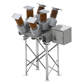
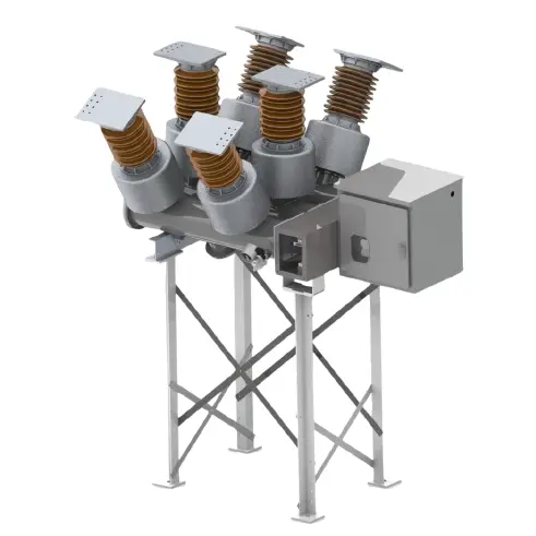
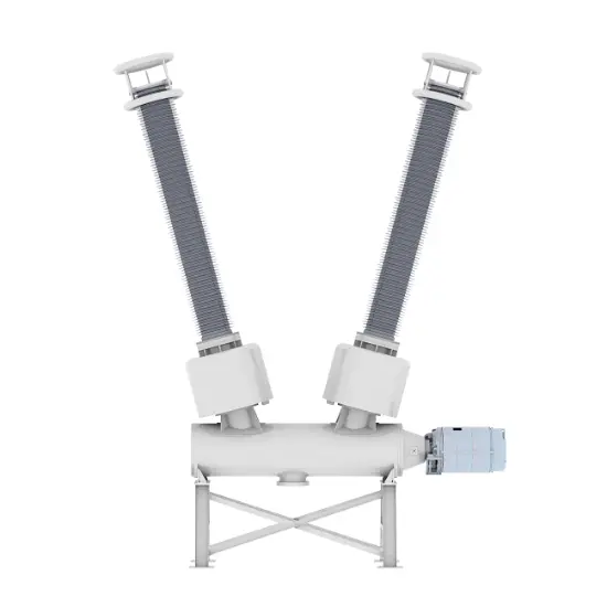
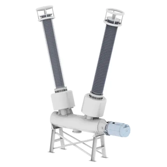
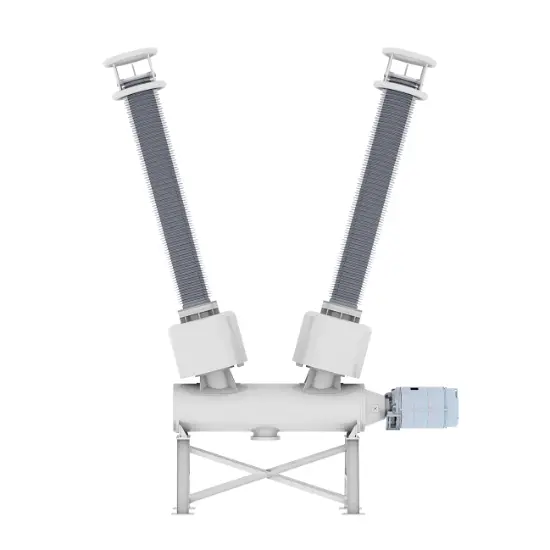
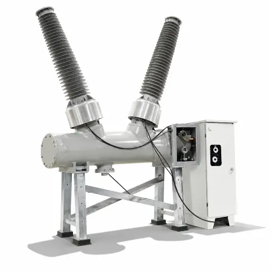
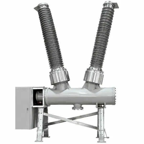
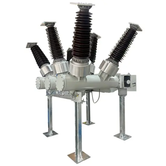
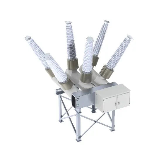
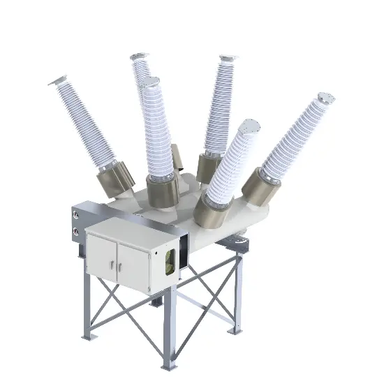
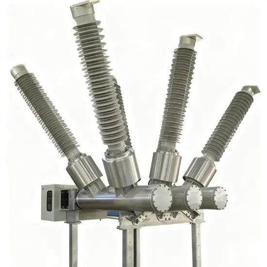
The RHD Series Dead-Tank SF6 Circuit Breaker is engineered for 'customized high-voltage power system solutions', covering standard voltage grades from RHD-40.5 to RHD-550 and supporting 'non-standard voltage customization' to precisely match your unique grid upgrade or construction needs. As a dead-tank type, its grounded tank isolates high-voltage components, ensuring superior insulation performance and safety--making it the go-to choose for demanding high-voltage scenarios.
About customization
We offer full customization services for voltage classes, including single-phase, two-phase, and three-phase configurations, as well as non-standard voltage/current solutions. Examples of available voltage and current specifications include 1250 A 75 kV, 3200 A 46 kV, 60 kV, 69 kV, and 75 kV (we support customization ranging from 10 kV to 800 kV for voltage and 1250 A to 6300 A for current). Regardless of your power grid's voltage specifications, we tailor the circuit breaker for seamless integration.
All products are fully assembled and tested at our factory before being shipped directly to your site--no disassembly of key components is required. This eliminates the need for on-site high-voltage testing, significantly saving you time and costs.
Key features
1. Superior Seismic Resistance
Adopting a low-center-of-gravity design, the breaker can withstand an earthquake intensity of up to 9 degrees, ensuring stable performance in seismic-prone areas--consistent with the RHD series' proven anti-seismic capability.
2. Excellent Arc-Extinguishing Performance & Long Service Life
Leveraging the high arc-extinguishing efficiency of SF6 gas, the breaker achieves a rated short-circuit breaking current of ≥50kA. It boasts an electrical life of more than 20 operations and a mechanical life of up to 10,000 cycles, significantly reducing equipment replacement and maintenance costs.
3. Low SF6 Gas Leakage Rate
The hermetic metal tank structure minimizes SF6 gas leakage, with an annual leakage rate of ≤1%--far below industry averages. This design not only avoids safety hazards from gas leakage but also reduces environmental impact.
4. Modular Design & Flexible Expansion
It supports on-demand configuration of built-in current transformers (CTs), with up to 15 CTs available for measurement or protection purposes. The standardized module interface allows flexible combination to meet diverse substation design and layout requirements, especially suitable for space-constrained scenarios.
5. Strong Environmental Adaptability
The breaker operates stably in extreme conditions: ambient temperature ranging from -40℃ to +55℃, maximum daily temperature difference of 32K, altitude up to 3,000m, and air pollution level up to Class IV. It also resists wind pressure of 700Pa (equivalent to 34m/s wind speed) and icing thickness of up to 20mm.
6. Comprehensive Safety Protection
Equipped with anti-mis operation interlocking devices, it effectively prevents accidents caused by incorrect operations. Before delivery, the breaker undergoes lightning impulse tests to eliminate insulation discharge risks from production and assembly, ensuring reliable quality.
7. Maintenance-Free Operating Mechanism
It adopts a spring-operated mechanism that is oil-free, gas-free, and maintenance-free. This mechanism delivers stable performance, low noise, and high reliability, reducing long-term operational workload.
Technology Parameters
| Item | Unit | Parameters | |||
| customization of Rated Voltage | kV | 3.6 kV/4.76 kV/7.2 kV/8.25 kV/12 kV /13.2 kV/11kV/12kV/13.8kV/15kV/15.5 kV /17.5 kV/22kV/22.9 kV/24 kV/25.8 kV/27 kV/33kV/36 kV/38 kV/40.5 kV/44kV/60kV/63kV/66kV/69kV/88kV/115kV/123kV/125kV/126kV/132kV/138kV/145kV/ 150kV/170kV/184kV/204kV/220kV/225kV/230kV/245kV/275kV/330kV/345kV/400kV/765kV/800kV |
|||
| customization of Rated current | A | 1250 to 6300 | |||
| Rated frequency | Hz | 50/60 | |||
| 1min Power frequency withstand voltage | kV | Max to 750 | |||
| Lightning impulse withstand voltage | kV | Max to 1675 | |||
| First open pole factor | 1.5/1.3/1.55 | ||||
| Rated short circuit breaking current | kA | 16 to 63 | |||
| Rated short - circuit duration | s | 4,3 | |||
| Rated out - of - phase breaking current | 10 | ||||
| Rated cable charging current | 10/50/125 | ||||
| Rated peak value withstand current | kA | 80/100/125 | |||
| Rated making current (peak) | kA | 80/100/125 | |||
| Creepage distance | mm/kV | 25 - 31 | |||
| SF6 gas leakage rate (per year) | ≤1% | ||||
| Rated SF6 gas pressure(20℃ gauge pressure) | Mpa | 0.5/0.4,0.5,0.6 | |||
| Alarm/blocking pressure(20℃ gauge pressure) | Mpa | 0.45/0.4,0.35/0.33,0.45/0.40,0.55/0.50 | |||
| SF6 annual gas leakage rate | ≤0.5 | ||||
| Gas moisture content | Ppm(v) | ≤150 | |||
| Heater voltage | AC220/DC220 | ||||
| Voltage of control circuit | DC | DC110/DC220/DC230 | |||
| Voltage of energy - store motor | V | DC 220/DC 110/AC 220/DC230 | |||
| Applied standards | GB/T 1984/IEC 62271 - 100 | ||||
| Name | unit | Parameters | |||
| Opening time | ms | 27±3 | |||
| Closing time | ms | 90±9 | |||
| Minute and conjunction time | ms | 300 | |||
| Together--ivide the time | ms | ≤60 | |||
| Simultaneity of opening | ms | ≤3 | |||
| Closing simultaneity | ms | ≤5 | |||
| Moving contact stroke | mm | 150+2-4 | |||
| Contact contact stroke | mm | 27±4 | |||
| Opening speed | m/s | 4.5±0.5 | |||
| Closing speed | m/s | 2.5±0.4 | |||
| Mechanical life | times | 6000 | |||
| Operation sequence | O - 0.3s - CO - 180s - CO | ||||
| Note: The opening and closing speed and time are the characteristic values of the circuitbreaker when it is single divided and closed under rated conditions. The closing speed is theaverage speed of the moving contact from the rigid closing point to 10 ms before closing, andthe opening speed is the average speed of the moving contact within 10 ms from the justequinox to 10 ms after the separation. | |||||
Application Scenarios
Large Hub Substations
Ideal for 220kV+ key hub substations, the customized RHD breaker controls and protects main power circuits. Its non-standard voltage adaptability ensures seamless integration into existing or upgraded grid architecture.
New Energy Grid-Connection Systems
Suitable for high-voltage grid connections in wind and solar power bases. Custom voltage ratings ensure reliable integration of renewable energy into the main grid, even in projects with unique voltage requirements.
Industrial High-Voltage Power Systems
Perfect for heavy industries (metallurgy, chemicals) with specialized voltage needs. The breaker’s robust performance and customizability guarantee stable power supply for high-power industrial equipment.
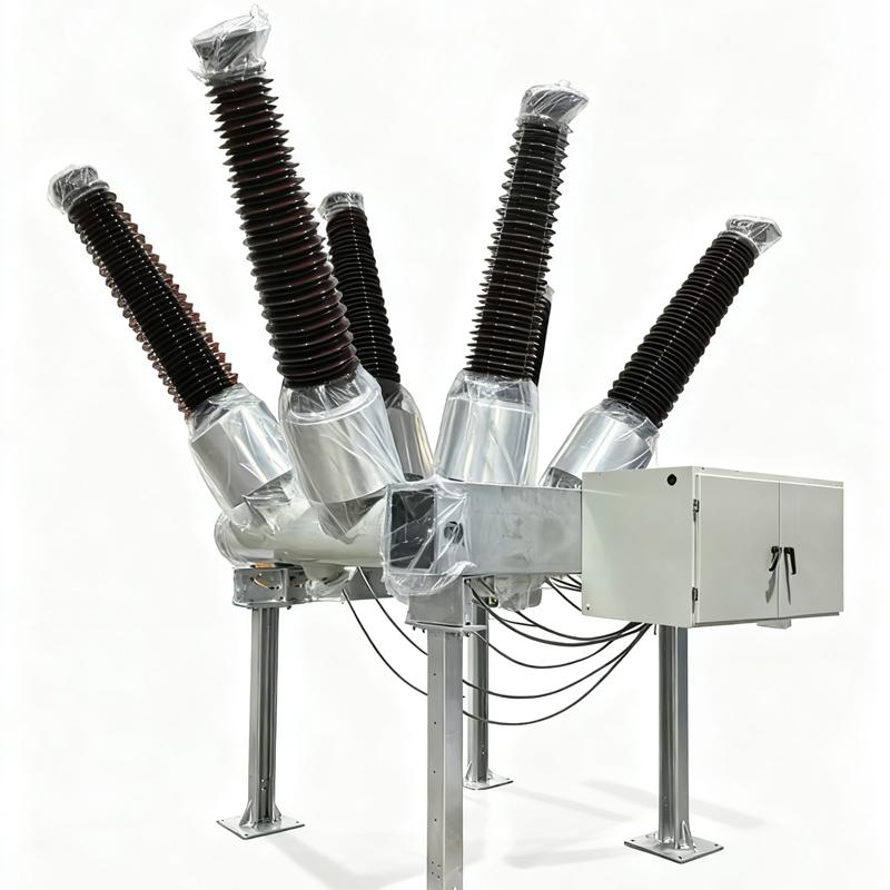
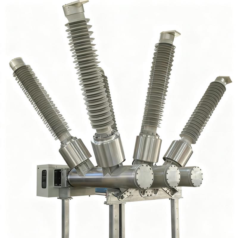
Tam Tank Yapısı: Kesici aralığındaki körük söndürme odası, yalıtım ortamı ve ilgili bileşenler, bir yalıtım gazı (örneğin, sülfür hekzaflorür) veya yalıtım yağı ile doldurulmuş metal tank içinde mühürlenir. Bu, nispeten bağımsız ve mühürlü bir alan oluşturarak, iç bileşenleri etkileyebilecek dış çevresel faktörleri etkili bir şekilde önler. Bu tasarım, ekipmanın yalıtım performansını ve güvenilirliğini artırır, çeşitli sert dış ortamlara uygun hale getirir.
Körük Söndürme Odası Düzeni: Körük söndürme odası genellikle tankın içinde yerleştirilir. Yapı, sınırlı bir alanda etkili körük söndürmeyi sağlayacak şekilde kompakt olarak tasarlanmıştır. Farklı körük söndürme ilkelerine ve teknolojilerine bağlı olarak, körük söndürme odasının spesifik yapısı değişebilir, ancak genellikle kontaktlar, püskürtücüler ve yalıtım malzemeleri gibi ana bileşenleri içerir. Bu bileşenler, kesici akımı keserken körüğü hızlı ve etkili bir şekilde söndürmek için birlikte çalışır.
İşletme Mekanizması: Yayla çalışan mekanizmalar ve hidrolikle çalışan mekanizmalar yaygın olarak kullanılan mekanizmalardır.
Yayla Çalışan Mekanizma: Bu tür mekanizma yapısal olarak basit, oldukça güvenilir ve bakım kolaydır. Yayların enerji depolama ve serbest bırakma yoluyla kesicinin açma ve kapatma işlemlerini sağlar.
Hidrolikle Çalışan Mekanizma: Bu mekanizma, yüksek çıkış gücü ve düzgün çalışma avantajları sunar, bu nedenle yüksek gerilimli ve yüksek akımlı sınıf kesiciler için uygundur.
1. Güç ağı seviyesine göre nominal voltajla eşleşen devre kesiciyi seçin
Standart voltaj (40.5/72.5/126/170/245/363/420/550/800/1100kV) güç ağı ile uygun nominal voltajla eşleştirilir. Örneğin, 35kV güç ağı için 40.5kV devre kesici seçilir. GB/T 1984/IEC 62271-100 gibi standartlara göre, nominal voltajın güç ağının maksimum çalışma voltajından ≥ olması sağlanır.
2. Standart olmayan özelleştirilmiş voltaj uygulama senaryoları
Standart olmayan özelleştirilmiş voltaj (52/123/230/240/300/320/360/380kV), eski güç ağı yenileme ve belirli endüstriyel güç senaryoları gibi özel güç ağı için kullanılır. Uygun standart voltajın olmaması nedeniyle üreticiler güç ağı parametrelerine göre özelleştirmek zorundadır ve özelleştikten sonra yalıtım ve arka söndürme performansının doğrulanması gerekir.
3. Yanlış voltaj seviyesini seçmenin sonuçları
Düşük bir voltaj seviyesi seçilmesi yalıtım çökertmesine neden olabilir, bu da SF sızıntısına ve ekipman hasarına yol açar; Yüksek bir voltaj seviyesi seçilmesi maliyetleri önemli ölçüde artırır, işletim zorluklarını artırır ve ayrıca performans uyumsuzluğu sorunlarına da neden olabilir.








 Giriş
Giriş