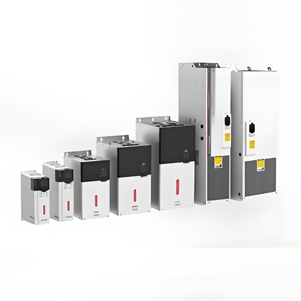
Common Methods for VFD Repair

RW Energy
13yrs +
staff 30000+m² US$100,000,000+ China
- Preparation Before Repair
- Safety Measures
- Power off the VFD and verify capacitor discharge is complete (use a multimeter to check DC bus voltage is below 36V).
- Wear insulated gloves and safety goggles to prevent electric shock or component explosion.
- Tool Preparation
- Multimeter, oscilloscope, LCR meter (bridge meter), insulation tester, screwdrivers, soldering station, etc.
- Fault Diagnosis
- Check the fault code on the VFD display (e.g., Overcurrent (OC), Overvoltage (OV), Overheating (OH)).
- Record fault phenomena (e.g., failure to start, unstable output, abnormal noise).
II. Common Faults and Repair Methods
- Power Supply Failure
- Phenomenon: No display, cannot power on.
- Possible Causes:
- Input power phase loss or unstable voltage.
- Damaged rectifier bridge, fuse, or filter capacitor.
- Repair Steps:
- Check if input power voltage is normal (380V/220V).
- Use a multimeter to check if the rectifier bridge is shorted; replace damaged rectifier modules.
- Inspect filter capacitors for bulging or leakage; replace failed capacitors.
- Overcurrent (OC Fault)
- Phenomenon: Frequent overcurrent alarms during operation.
- Possible Causes:
- Motor short circuit, poor insulation, or excessive load.
- Faulty current detection circuit (e.g., damaged Hall sensor).
- Drive circuit abnormality (damaged IGBT module).
- Repair Steps:
- Disconnect the motor and test the VFD under no-load conditions.
- Check motor winding insulation resistance (using a megohmmeter).
- Test IGBT module for short circuits (measure pin-to-pin resistance using the diode test function).
- Inspect drive circuit components (opto-isolators, resistors, capacitors) for damage.
- Overvoltage (OV Fault)
- Phenomenon: Overvoltage alarm during deceleration.
- Possible Causes:
- Faulty braking resistor or braking unit.
- Deceleration time setting too short, preventing regenerative energy release.
- Repair Steps:
- Check if braking resistance value is normal (infinite resistance if burnt out).
- Extend deceleration time (via parameter adjustment).
- Test if the braking unit triggers correctly.
- Overheating (OH Fault)
- Phenomenon: Overheating alarm after operating for some time.
- Possible Causes:
- Cooling fan jammed or damaged.
- Excessive dust buildup on heat sink, poor ventilation.
- Temperature sensor failure.
- Repair Steps:
- Clean the heat sink and air vents.
- Test fan voltage; replace damaged fan if necessary.
- Check temperature sensor resistance for abnormalities.
- Communication Fault
- Phenomenon: Unable to communicate with PLC or host computer.
- Possible Causes:
- Poor contact at communication port connections.
- Incorrect communication protocol or baud rate settings.
- Damaged isolation chip (e.g., RS485 chip).
- Repair Steps:
- Check terminal connections for looseness or oxidation.
- Verify parameter settings (e.g., Modbus address, baud rate).
- Replace damaged communication chip.
- Parameter Setting Error
- Phenomenon: Abnormal motor operation (e.g., reverse rotation, incorrect speed).
- Repair Steps:
- Restore factory settings and re-enter motor parameters (power, rated current, pole count, etc.).
- Check if the starting method (e.g., V/F control, vector control) is appropriate.
- Hardware Damage
- Common Vulnerable Components:
- Capacitors: Aged filter capacitors causing reduced capacitance or leakage.
- IGBT Modules: Shorted due to overcurrent or overheating.
- Drive Circuit: Damaged opto-isolators or gate resistors.
- Repair Methods:
- Replace components with identical specifications; pay attention to soldering temperature and time.
- Apply new thermal paste after module replacement to ensure proper heat dissipation.
III. Post-Repair Testing
- No-Load Test:
- Power on without motor connection; observe display and parameters for normalcy.
- Load Test:
- Connect motor; operate at low speed, gradually increase load; monitor output current and temperature.
- Extended Run Test:
- Operate continuously for 1-2 hours to confirm no abnormal alarms occur.
IV. Preventive Maintenance
- Periodically clean internal dust and inspect cooling fans.
- Tighten power and motor terminal connections to prevent poor contact.
- Test capacitor capacitance and insulation resistance every six months.
- Update VFD firmware (if newer versions are available).
V. Precautions
- Safety First: Working on live equipment is absolutely prohibited; capacitor discharge must be thorough.
- Component Replacement: IGBT modules must match the required voltage, current rating, and package type.
- Professional Support: For complex faults (e.g., chip-level repair), contact the manufacturer or a specialized service provider.
Through systematic troubleshooting and targeted repairs, most VFD faults can be effectively resolved. If problems persist, further analysis using circuit diagrams to trace signal flow and locate hidden faults is necessary.
08/21/2025
Recommended
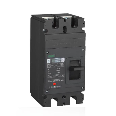
Application of New DC Circuit Breakers in Short-Circuit Fault Protection
I. IntroductionWith the rapid advancement of modern information technology, intelligence has become a major trend in the development of industrial equipment. In the field of high-voltage switching, intelligent circuit breakers—as critical control components in power systems—form the foundation for automation and intelligence in power systems. This study focuses on an intelligent DC circuit breaker based on single-chip microcomputer (SCM) technology, emphasizing its practical applica
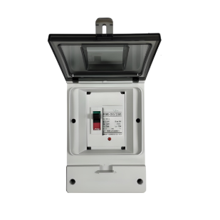
Application Solutions of DC Circuit Breakers in the New Energy Sector
I. OverviewWith the rapid development of new energy power generation and electric vehicle (EV) charging facilities, DC systems have imposed higher requirements for safety protection equipment. Traditional AC circuit breakers cannot effectively interrupt DC fault currents, creating an urgent need for specialized DC circuit breaker solutions. This solution provides professional protection configurations for two major application scenarios: photovoltaic (PV) power generation systems and EV chargin
Low-Cost, Low-Loss DC Arc-Free Circuit Breaker Solution for Rail Transit
I. Solution OverviewThis solution addresses the protection needs of DC systems (particularly rail transit traction power supply) against short-circuit faults by proposing a DC circuit breaker solution based on optimized mechanical breaker structure. It achieves arc-free interruption through capacitor voltage control, combining low on-state loss and high reliability, making it suitable for frequent operation scenarios.II. Core PrincipleUtilizes a fast mechanical switch topology combined with p
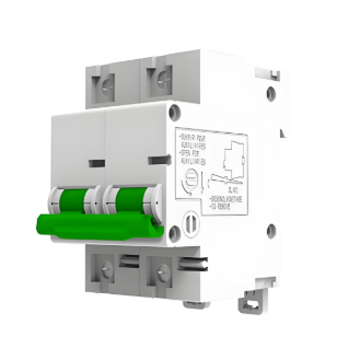
PEBS Circuit Breaker DC Safety Solution
Solution OverviewIn modern renewable energy power systems, such as photovoltaic (PV) power generation and energy storage systems, fault protection on the DC side is a core element for ensuring safe, stable, and efficient operation. The Projoy PEBS series DC miniature circuit breakers are specifically designed for such applications, providing a comprehensive and efficient solution integrating arc control, overload protection, and short-circuit protection. This solution aims to deliver the highes
About
RW Energy
Zhejiang Rockwell Energy Technology Co., Ltd.
13yrs +
staff 30000+m² US$100,000,000+ China


