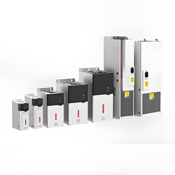
Common Methods for VFD Repair

- Preparation Before Repair
- Safety Measures
- Power off the VFD and verify capacitor discharge is complete (use a multimeter to check DC bus voltage is below 36V).
- Wear insulated gloves and safety goggles to prevent electric shock or component explosion.
- Tool Preparation
- Multimeter, oscilloscope, LCR meter (bridge meter), insulation tester, screwdrivers, soldering station, etc.
- Fault Diagnosis
- Check the fault code on the VFD display (e.g., Overcurrent (OC), Overvoltage (OV), Overheating (OH)).
- Record fault phenomena (e.g., failure to start, unstable output, abnormal noise).
II. Common Faults and Repair Methods
- Power Supply Failure
- Phenomenon: No display, cannot power on.
- Possible Causes:
- Input power phase loss or unstable voltage.
- Damaged rectifier bridge, fuse, or filter capacitor.
- Repair Steps:
- Check if input power voltage is normal (380V/220V).
- Use a multimeter to check if the rectifier bridge is shorted; replace damaged rectifier modules.
- Inspect filter capacitors for bulging or leakage; replace failed capacitors.
- Overcurrent (OC Fault)
- Phenomenon: Frequent overcurrent alarms during operation.
- Possible Causes:
- Motor short circuit, poor insulation, or excessive load.
- Faulty current detection circuit (e.g., damaged Hall sensor).
- Drive circuit abnormality (damaged IGBT module).
- Repair Steps:
- Disconnect the motor and test the VFD under no-load conditions.
- Check motor winding insulation resistance (using a megohmmeter).
- Test IGBT module for short circuits (measure pin-to-pin resistance using the diode test function).
- Inspect drive circuit components (opto-isolators, resistors, capacitors) for damage.
- Overvoltage (OV Fault)
- Phenomenon: Overvoltage alarm during deceleration.
- Possible Causes:
- Faulty braking resistor or braking unit.
- Deceleration time setting too short, preventing regenerative energy release.
- Repair Steps:
- Check if braking resistance value is normal (infinite resistance if burnt out).
- Extend deceleration time (via parameter adjustment).
- Test if the braking unit triggers correctly.
- Overheating (OH Fault)
- Phenomenon: Overheating alarm after operating for some time.
- Possible Causes:
- Cooling fan jammed or damaged.
- Excessive dust buildup on heat sink, poor ventilation.
- Temperature sensor failure.
- Repair Steps:
- Clean the heat sink and air vents.
- Test fan voltage; replace damaged fan if necessary.
- Check temperature sensor resistance for abnormalities.
- Communication Fault
- Phenomenon: Unable to communicate with PLC or host computer.
- Possible Causes:
- Poor contact at communication port connections.
- Incorrect communication protocol or baud rate settings.
- Damaged isolation chip (e.g., RS485 chip).
- Repair Steps:
- Check terminal connections for looseness or oxidation.
- Verify parameter settings (e.g., Modbus address, baud rate).
- Replace damaged communication chip.
- Parameter Setting Error
- Phenomenon: Abnormal motor operation (e.g., reverse rotation, incorrect speed).
- Repair Steps:
- Restore factory settings and re-enter motor parameters (power, rated current, pole count, etc.).
- Check if the starting method (e.g., V/F control, vector control) is appropriate.
- Hardware Damage
- Common Vulnerable Components:
- Capacitors: Aged filter capacitors causing reduced capacitance or leakage.
- IGBT Modules: Shorted due to overcurrent or overheating.
- Drive Circuit: Damaged opto-isolators or gate resistors.
- Repair Methods:
- Replace components with identical specifications; pay attention to soldering temperature and time.
- Apply new thermal paste after module replacement to ensure proper heat dissipation.
III. Post-Repair Testing
- No-Load Test:
- Power on without motor connection; observe display and parameters for normalcy.
- Load Test:
- Connect motor; operate at low speed, gradually increase load; monitor output current and temperature.
- Extended Run Test:
- Operate continuously for 1-2 hours to confirm no abnormal alarms occur.
IV. Preventive Maintenance
- Periodically clean internal dust and inspect cooling fans.
- Tighten power and motor terminal connections to prevent poor contact.
- Test capacitor capacitance and insulation resistance every six months.
- Update VFD firmware (if newer versions are available).
V. Precautions
- Safety First: Working on live equipment is absolutely prohibited; capacitor discharge must be thorough.
- Component Replacement: IGBT modules must match the required voltage, current rating, and package type.
- Professional Support: For complex faults (e.g., chip-level repair), contact the manufacturer or a specialized service provider.
Through systematic troubleshooting and targeted repairs, most VFD faults can be effectively resolved. If problems persist, further analysis using circuit diagrams to trace signal flow and locate hidden faults is necessary.
08/21/2025
Recommended

Integrated Wind-Solar Hybrid Power Solution for Remote Islands
AbstractThis proposal presents an innovative integrated energy solution that deeply combines wind power, photovoltaic power generation, pumped hydro storage, and seawater desalination technologies. It aims to systematically address the core challenges faced by remote islands, including difficult grid coverage, high costs of diesel power generation, limitations of traditional battery storage, and scarcity of freshwater resources. The solution achieves synergy and self-sufficiency in "power suppl

An Intelligent Wind-Solar Hybrid System with Fuzzy-PID Control for Enhanced Battery Management and MPPT
AbstractThis proposal presents a wind-solar hybrid power generation system based on advanced control technology, aiming to efficiently and economically address the power needs of remote areas and special application scenarios. The core of the system lies in an intelligent control system centered around an ATmega16 microprocessor. This system performs Maximum Power Point Tracking (MPPT) for both wind and solar energy and employs an optimized algorithm combining PID and fuzzy control for precise

Cost-Effective Wind-Solar Hybrid Solution: Buck-Boost Converter & Smart Charging Reduce System Cost
AbstractThis solution proposes an innovative high-efficiency wind-solar hybrid power generation system. Addressing core shortcomings in existing technologies—such as low energy utilization, short battery lifespan, and poor system stability—the system employs fully digitally controlled buck-boost DC/DC converters, interleaved parallel technology, and an intelligent three-stage charging algorithm. This enables Maximum Power Point Tracking (MPPT) over a wider range of wind speeds and s
Hybrid Wind-Solar Power System Optimization: A Comprehensive Design Solution for Off-Grid Applications
Introduction and Background1.1 Challenges of Single-Source Power Generation SystemsTraditional standalone photovoltaic (PV) or wind power generation systems have inherent drawbacks. PV power generation is affected by diurnal cycles and weather conditions, while wind power generation relies on unstable wind resources, leading to significant fluctuations in power output. To ensure a continuous power supply, large-capacity battery banks are necessary for energy storage and balance. However, bat


