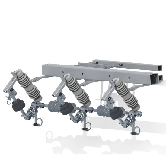
| Brand | Rw Energy |
| Series | RDK |
| Rated voltage | 38kV |
| Rated frequency | 60 Hz / 50 Hz (Selectable) |
| Rated continuous current | 100A/200A/300A |
| Pickup (programmable) | 16–480 A(7 gears) |
| Current accuracy | ±5% |
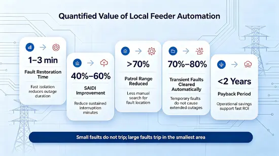
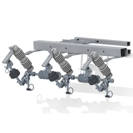
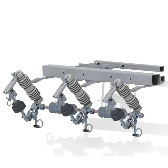
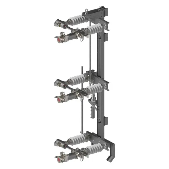
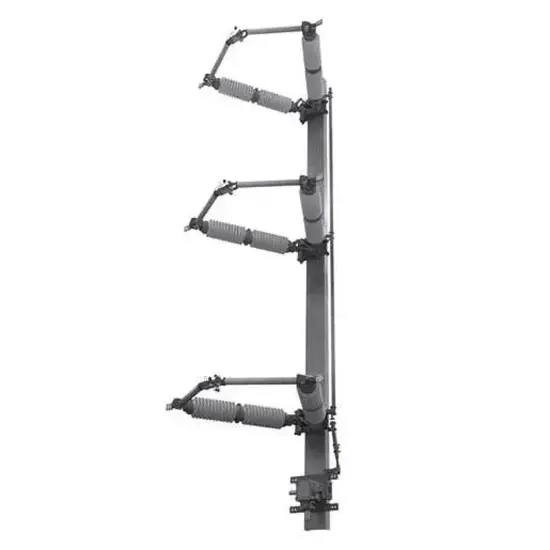
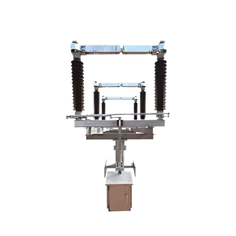
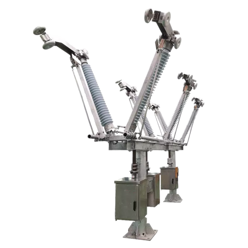
The RDK-38/300, developed by Zhejiang Rockwell Energy for domestic and overseas 38 kV, 50/60 Hz distribution systems, coordinates with reclosers or autoreclosing breakers to confine outages to the faulted segment . Because it distinguishes transient from permanent faults by counting fault-current events, it acts only on permanent faults — transient faults reset automatically after the programmable memory time (30–300 s) (p.3). Because its electronic controller is powered by line-current induction instead of an external auxiliary supply, it needs no PT, no batteries and no routine maintenance — main-circuit resistance ≤300 μΩ, current measurement accuracy ±5% .
| Parameter | Value |
| Rated voltage | 38 kV |
| Rated frequency | 60 Hz / 50 Hz (Selectable) |
| Rated continuous current | 100A/200A/300 A |
| Minimum line current | 10 A |
| Current accuracy | ±5% |
| Main-circuit resistance | ≤300 μΩ |
| Pickup (programmable) | 16–480 A(7 gears) |
| Counts (programmable) | 1 / 2 / 3 / 4 |
| Reset (memory) time | 30–300 s( 1 s) |
| Ambient temperature | -40 ℃ ~ +60 ℃ |
| Altitude / Wind pressure | ≤2,000 m / ≤700 Pa |
| USB port | IP68 |
| Event log | 100 records, Excel export |
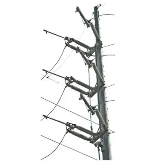
1.On long main lines with multiple branches, faults risk tripping the substation breaker and blacking out the whole feeder. Installed at branch/segment points, the RDK-38/300 resets automatically on transient faults and drops out load-free on permanent ones, isolating only the faulted branch .
2.With a 1-fast-3-slow substation recloser and sectionalizers set F1=3, F2/F3/F5=2, F4/F6=1 counts, any of 7 line segments is isolated on fault and the recloser restores the other six
3.Requiring no communication channel and no external supply, it fits remote lines without 4G or a master station, supporting local (non-communication) feeder automation
1.After closing by hookstick, counting starts once line current exceeds pickup .
2.When the upstream recloser trips and the line de-energizes — because the sectionalizer drops out only when load-free, its contacts fall safely to create a visible isolation gap.
3.After the programmed counts (1–4), the controller energizes the mechanism coil, releasing the pre-charged detent; the section drops out and the recloser restores healthy sections .
4.Transient faults never reach the count threshold — because the counter resets after the memory time (30–300 s), no crew visit is needed.
FAQ — 38 kV Drop-Out Sectionalizer (RDK-38/300)
Five questions from utilities and independent power producers applying 38 kV class sectionalizers on 33 kV sub-transmission lines and solar PV points of interconnection.
Both, but for different reasons. On a 33 kV trunk line, the justification is exposure: these feeders are longer, more scattered and harder to patrol than 11 kV spurs, so a permanent fault that trips the source breaker removes supply from industrial, mining or water-pumping load over a wide area; sectionalising the trunk converts one network-wide interruption into a single-section interruption. At a PV point of interconnection, the collector feeder is a radial circuit like any other, and it benefits from the same treatment — provided the coordination accounts for power flowing in both directions. What does not change with voltage is the physical division of labour: the sectionalizer is an isolating device that carries fault current and opens only after the upstream recloser has cleared it, in the de-energised interval. At 33 kV and 38 kV the fault levels, clearances and mechanical loads are all larger, so the withstand, creepage and mounting calculations carry more weight — but the device is still, and must be specified as, a non-fault-breaking isolator.
Because air insulation weakens as air density falls. The dielectric strength of an air gap depends on gas density, and as altitude rises the density drops for a given gap and temperature; as an engineering approximation, withstand falls by roughly 1 % per 100 m above 1,000 m, with the exact correction factor taken from IEC 60071-2. At 3,500 m that is of the order of a 25 % reduction relative to sea level, which is enough to make a standard impulse level marginal on a 36 kV class assembly — hence the practice of specifying an enhanced impulse withstand, such as the 200 kV BIL used on RW Energy's 33 kV highland projects, where the insulation was dimensioned with an altitude correction rather than a nameplate rating. The correction applies to external clearances as well as to the declared level, because it is the air path, not the test certificate, that withstands the surge. When the site is between 2,000 m and 3,500 m, the altitude basis must be stated in the specification, since type tests are normally performed near sea level and the project must apply the correction itself.
At 700 Pa — 700 N/m² of projected area — the wind load on the interrupter, insulator and jumper is no longer a secondary effect, and it acts on a structure that is already carrying conductor tension. The checks that matter are: the cantilever bending moment at the mounting, calculated from wind pressure on the unit's projected area plus the conductor load applied at the terminal; the conductor tension itself, which rises in cold weather and with span length; and oscillation, since a long span can set up low-frequency motion that works on the assembly and its hinge. Three practical measures reduce the risk. Use a jumper loop at the terminal so conductor tension is taken by the line, not by the device's cantilever. Verify the bracket and crossarm as part of the same calculation as the unit, because the weakest element usually sets the limit. And confirm the mechanical ratings of the 38 kV assembly — mounting strength and the relevant mechanical type test evidence — with the product department for the specific project, rather than assuming that ratings verified for a lower voltage class carry across.
Counting is triggered by current magnitude crossing the actuating threshold, and the counter does not distinguish direction. On a PV collector feeder this has a direct setting consequence: the actuating current must be set above the maximum reverse (export) current as well as above the maximum forward load current, which narrows the setting window whenever the plant's export approaches the feeder's normal demand. There is a second, less obvious constraint: inverter fault current is deliberately limited, typically to about 1.1 to 1.5 times rated current, so a fault fed only from the inverter side can produce a current pulse that is uncomfortably close to the normal export level. Where those two levels close up, the sectionalizer is not the right instrument for the discrimination — the answer is to sectionalise the network side of the interconnection and let the point of interconnection protection do the discriminating, using its directional elements, while anti-islanding functions such as rate-of-change-of-frequency protection remain the responsibility of the interconnection scheme, not of the sectionalizer.
Four items, in sequence. Before energisation, a coordination study fixes three numbers: the actuating current against the recloser pickup, with the sectionalizer set at 80 % or below; the count at each position, from recloser trip operations − 1; and the timing margin, with counted operations on the recloser's delayed curve (> 0.5 s) and the memory time longer than the complete reclose sequence. At commissioning, the settings are read back from each unit and recorded, and the mechanical condition of the drop-out assembly is checked with the feeder de-energised. During operation, the recloser's system-level time-current verification — the complete assembly, its control and the interconnecting means, as required by IEC 62271-111 clause 7.108 — underpins the assumption that the sequence runs as designed. After the first natural fault, the sectionalizer's event log, which retains up to 100 records including the last trip current and the cycle count, shows whether the intended position dropped out and whether the healthy sections were restored. One safety rule is absolute and belongs in the commissioning procedure: the unit must never be used to close onto a fault, because closing into a fault can damage the device and endanger personnel.








 Login